My O Gauge Journal on
Modelling the GWR
A personal Journey
Gauge 1 Project
I decided to sell off most of my Hornby Dublo railway, (but keep a small selection of prized locos and track for the future). The proceeds would go towards creating a Gauge 1 railway. As it potentially requires a large space or indeed the garden, I looked to creating an 'L' shaped layout that would fit into a medium sized room. The initial description would take the form of:
A terminus country station with goods facilities. One road entrance to and from the station engine shed, signal box, station building, water tower, goods shed, and facilities for unloading cattle. Two small locos a 14xx and 48xx Prairie.
Minimum 6' radius points.
The points will be specially made with 6' turnouts.
The buildings come from Lasercut model railways, the locos from Tower models, and the points and wagon kits from Tenmille, (websites accessible from the top right of this page).
I have a water tower, signal box and engine shed built but yet to be painted and here they are:-
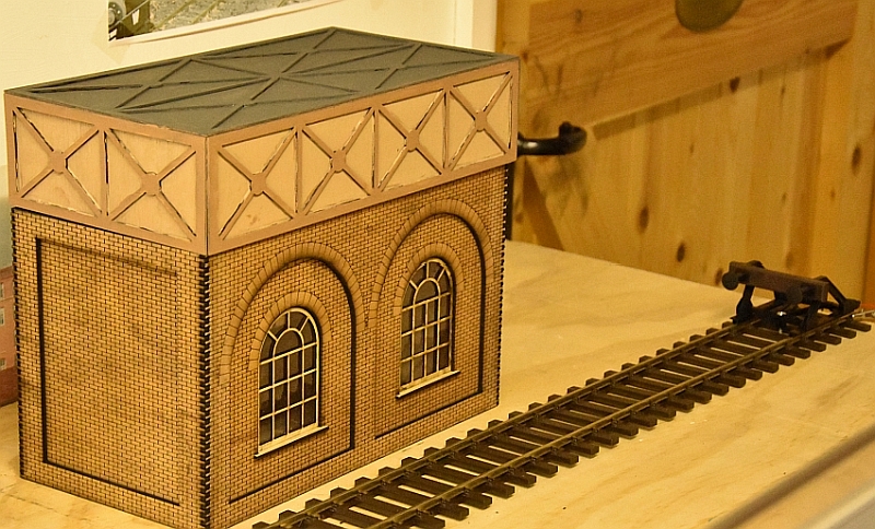
The Engine shed
Made a slight modification to the shed cutting it down to
three window sections as opposed to the 4 which it comes as.
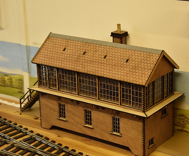
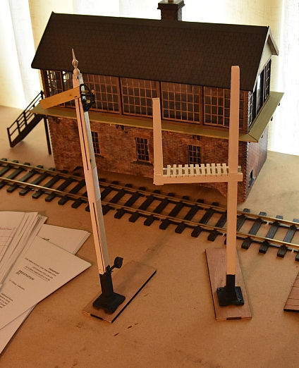
The signal box
The water tower
Station building low relief so I cut the building in half and doubled its size!
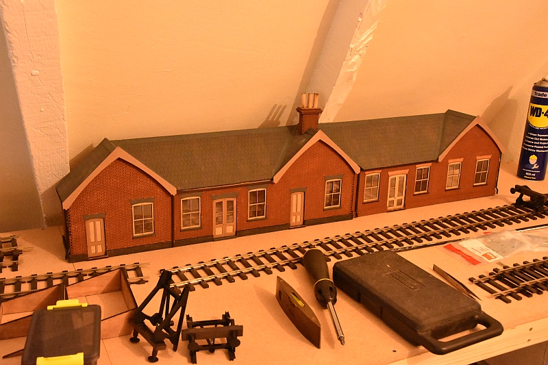
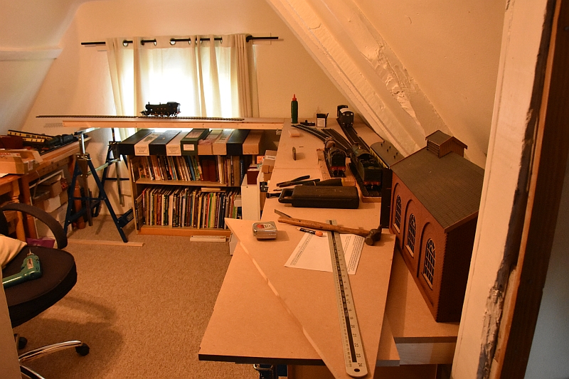
The goods shed and station building have also been constructed and require painting. A house move seems to be the ideal time to further this project considering the limited space available. I now have a room 3 metres by 3.5 metres to use for this purpose at the moment.
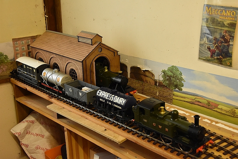
With the third loco, ( a pannier not due til May/June), that will complete the RC locos. Signalling i intend to build from Tenmille kits. My preference for buffer stops is to use the Marklin ones. No 5602 from Gaugemaster.
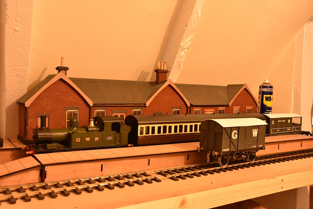
The station building now sitting on the platform structure with the small second platform in front of it. A sloping roof is not helpful though where space is at a premium. I am considering rotating the layout 90 degrees anticlockwise to give me back the lost space behind the station building and platform currently.
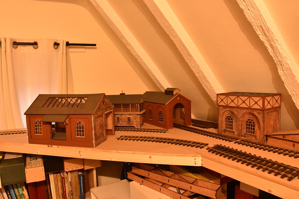
Having to increase the size of the corner piece to accommodate the goods shed. Here the buildings are lined up in their respective positions. The slope of the roof is limiting their positions though so I intend to move all anticlockwise to correct this.
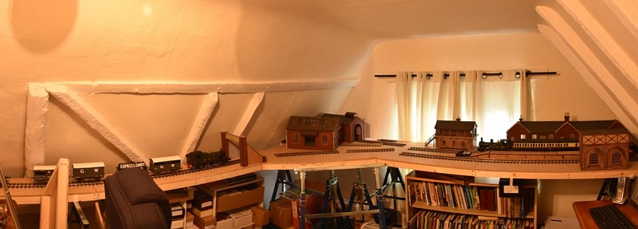
I know it looks a little bent but the pan-program I used to piece two photos together is the culprit! I can now use the full width of the baseboards along the station side of the layout.
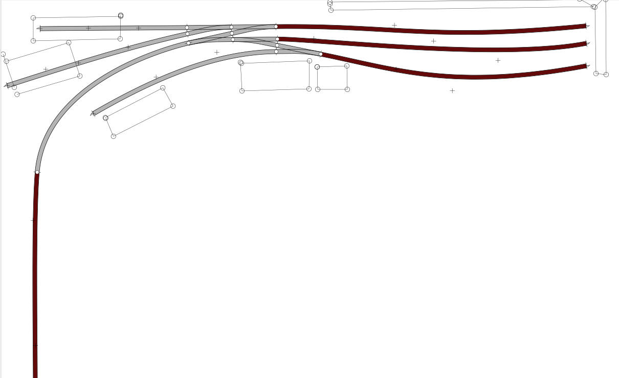
The size of the turnouts and their minimum curvature will be so important. I have Tenmille making up one point for a trial and three lengths of track. The PECO track will be dispensed with as it is not a good fit to their track and will be all brass. In the mean time i am building some signal kits for the railway.
As with most layouts, changes often come along. Putting all the buildings etc in the 'correct' places is often a puzzle game. Here is a new arrangement, the engine shed will be in the fore ground fed by a point in the station throat.
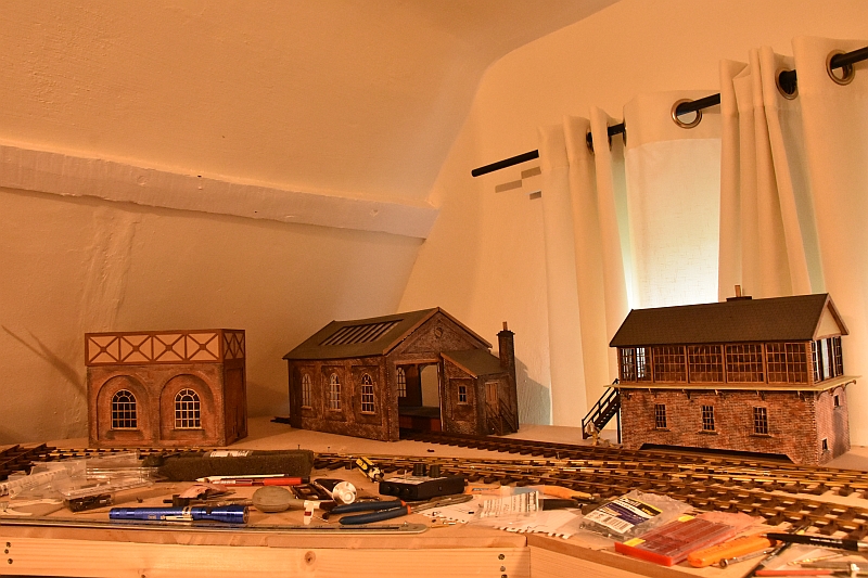
This arrangement allows the spectator to view almost every part of the railway easily.
The tight curves can be quite an issue for both the locos and the rolling stock. As far as rolling stock is concerned which is non-bogie then using Kaydee couplings in a particular way stops the buffers locking on the curves. I used O gauge couplings with long arms to give enough clearance, (#746s). They are unobtrusive as well.
As far as bogie rolling stock is concerned the bogies may need lifting slightly to allow them to pass under the chassis sides of the coach body. and again using Kaydee couplings will keep buffer lock at bay.
Finally the locos themselves may be fine but I fould that my 16xx had side play issues with its bogie. The tower model is essentially fixed and side play needs to be organised through the back to cack wheel distances. This says more about the point throat than anything else. Also the frog 'V' may need filling slightly to stop wheel drop. The combination of a wheel set dropping whilst riding up a rail will lead to derailments.
The next stage is where I start to look at electrifying the points and adding working signals. I have DCC concepts products to use and firstly to keep things simple i want a switch lever of theirs to control one of their turnout motors. This will need the use of a DPDT switch. On the Cobalt-s lever there are three sets of switches and the second and third switches can be used together to create a DPDT switch as follows:
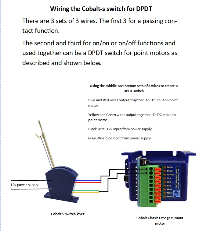
Click the above for a larger image.
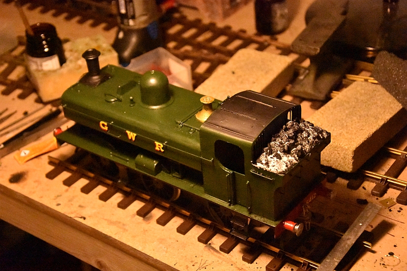
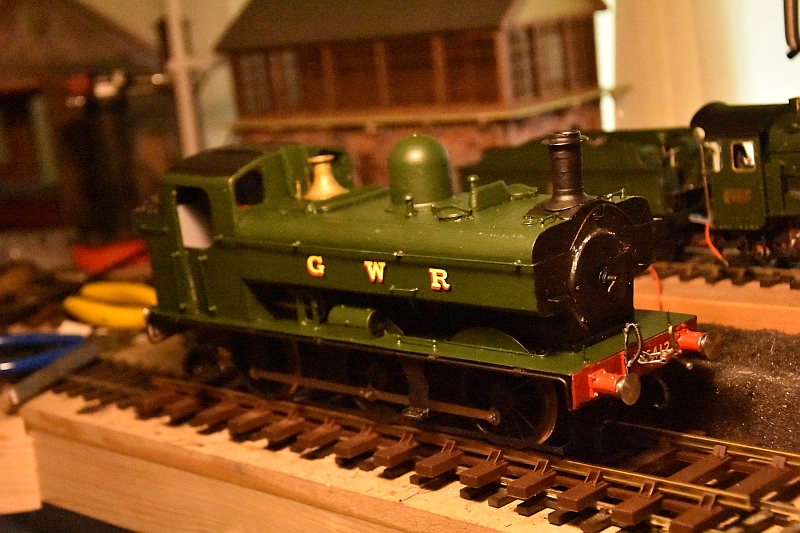
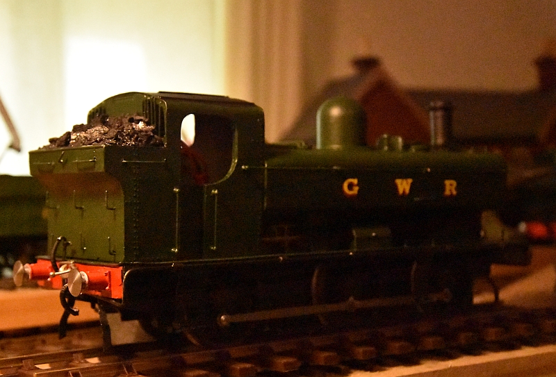
The third loco for the project is now here and just painted with extra detail such as steam pipes along the footplate.