O Gauge Modelling on the GWR
A personal Journey
Creating the ground gear for the Travelling post Office
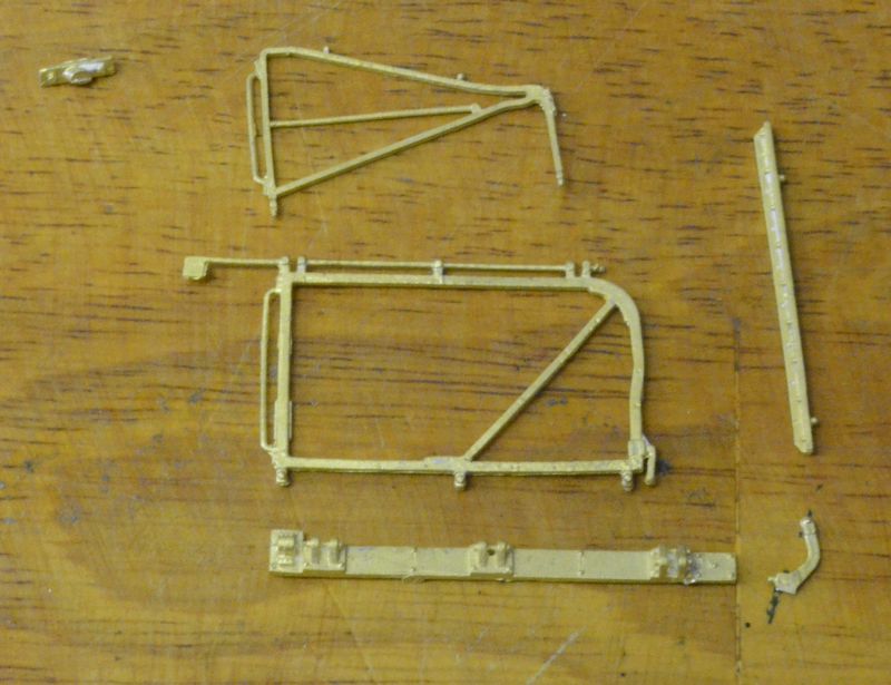
I have the diagrams from the Hosegood book for the ground framing as shown here. Given some measurements on the drawing I will be able to calculate the other necessary ones:
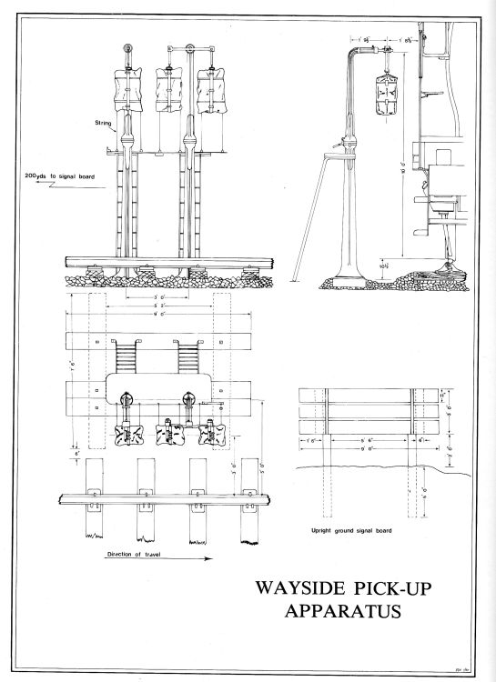
Unfortunately some of the key measurements are missing so I have had to use dividers to estimate the correct dimensions. Also there is some key information missing from the wayside pickup apparatus drawing. The bases of the pickup arms actually rest on two sleepers. The bases are circular and have four bolts holding the arm bases to the sleepers. As shown here. The lower step legs are at the same level as these sleepers and the whole arrangement is held together by two sleepers below as per the drawing. Once I have all the correct dimensions calculated I will transpose them onto the drawings shown above.
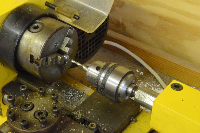
Putting together the component parts for the wayside pickup gear, may take some time. I have 2mm and 3mm brass pipe on order from Squires and for the swivel joint I propose to use some low carbon soft steel bearings commonly referred to as catapult ammo balls that are 9.5mm in diameter. These will need drilling to 3mm to accommodate the brass piping. This is easily achieved using a lathe to drill out each bearing. The balls were obtained as a pack of 10 from Simply Bearings Ltd for around £2.
As shown here, the easiest way to drill the correct size hole in the ball is to place it in the lathe chuck and use a drill chuck in the head stock. I used a 2mm drill placed well into the chuck so that the drill was only a couple of mm proud. This enabled me to make a starting hole in the ball. I then extended the drill and drilled into the ball until I was all the way through. Replace the 2mm drill with a 3mm drill and drill that through the ball.
The ball bearing will now accept a 3mm dia brass tube. This is one component part of my design for the wayside equipment. Two balls were modified like this.
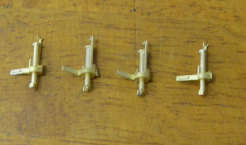
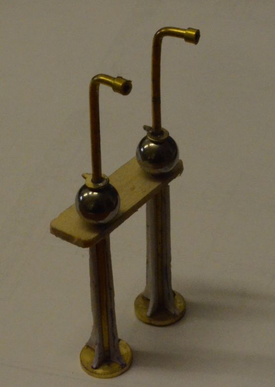
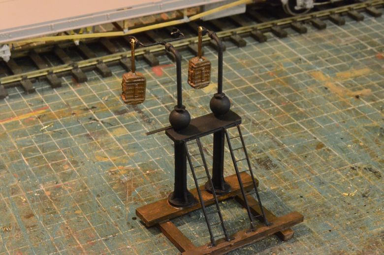
Here is a simple mock-up of the main component parts of the pickup apparatus to scale. The feet were turned on the lathe and are the diameter 1' 8".
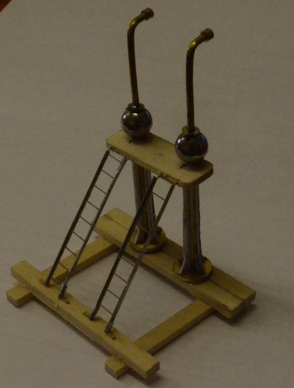
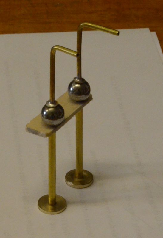 I have
modified the swivel arms so that they have handles as per the
prototype, (see below), and cut several planks to act as sleepers to
support the whole structure.
I have
modified the swivel arms so that they have handles as per the
prototype, (see below), and cut several planks to act as sleepers to
support the whole structure.
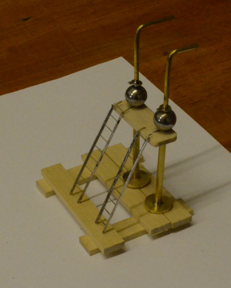
The two ladders are from a signal kit with strengthened sides. I will make brackets to secure these ladders underneath the platform and at the base as per drawings. The top half of the framing swivels around the ball joints. The small handles on the swivel arms are to be bent down and two slots cut in the back of the balls to allow these levers to secure the hangers stopping them from swivelling.
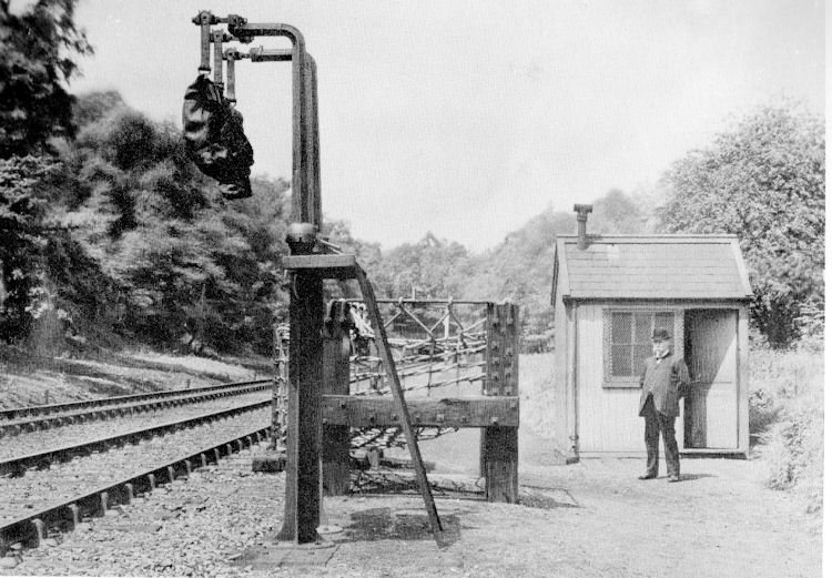
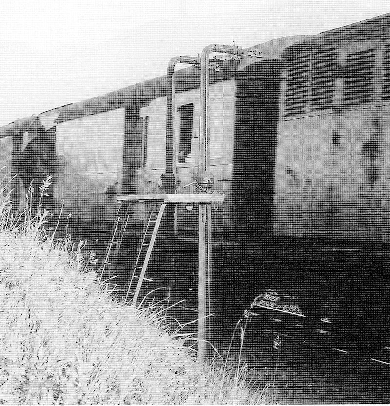
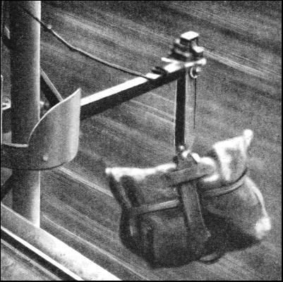
Interestingly enough the collection and pickup gear was not always together on the same track. This was so at Liskeard where the up line picked up the mail and the down line dropped the mail. Here is a part picture of the Liskeard post being picked up.
The TPO gear has arrived from JLTRT. Here is the net arrangement:
To make this work, I will have to remove some of the rodding drill into the brackets and replace with brass wire. Not an easy job but achievable. The same cannot be said of the bag supports, (called traductors), see below:
These are solid castings but In practice the arms move out, round and down from the carriage body. If I am to make these work a rebuild may well be necessary. I have 4 castings so I can experiment here. More on this later!
This is what the traductors looked like extended:
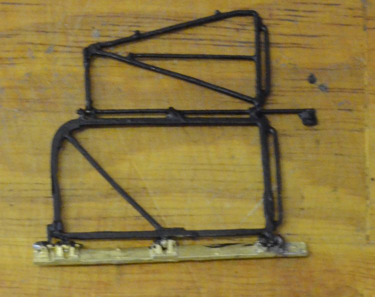
The net arrangement needed to be hinged in two places and the joints therefore would need to be drilled out. Not an easy job. This took a whole morning and necessitated the removal of cosmetic rods, drilling out bearing holes and replacing with brass wire. This having been accomplished I painted the arrangement with matt black paint as shown here. It will now fold flat against the coach side when not in use and can be extended when necessary to catch the mail bags.
The traductor arms also necessitated the grinding out the solid arm extensions to be replaced by moving ones. This I managed to do by drilling a hole in the bottom of the main bar to add in a small piece of rod on which the arm could rotate. Here they are with one arm in the down position and the other in the up position.
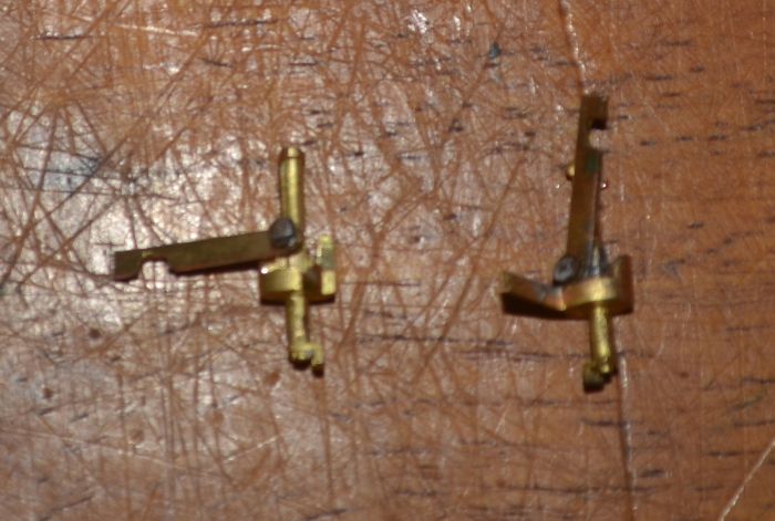
There is a left hand and right hand traductor.
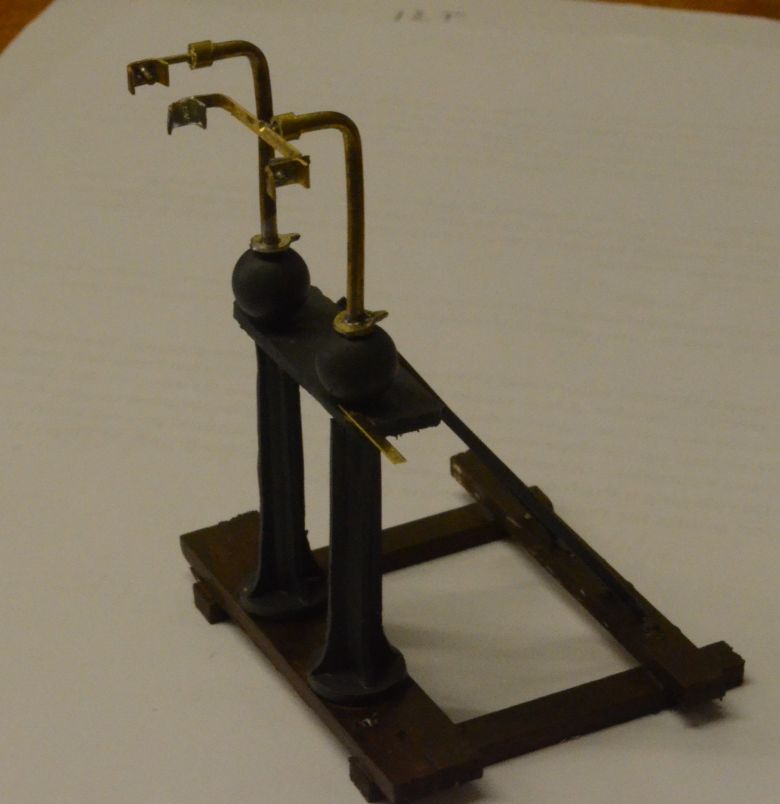
Back to the ground pickup apparatus. I've trimmed off the upper arms and given them bosses as per the photo also glued 'plastic' flutes to the lower arms. This almost completes this part of the apparatus.
After adding the flutes to the lower sections and cutting the limewood sleepers to the correct width and finishing off the ladders with securing strips at the bottom of each means that the whole thing can now be glued together. Here it is approximated to Hosegoods drawings.
Now for painting it a grey undercoat and adding the 'hanging' brackets. Based on available images they look like pegs inside a holding bracket. The net arrangement on the coach slips the bags off their mounts and literally 'thumps' them onto the coach holding area. It appears that a single and double bracket was often used so I have created one of each here.
You can see the levers clearly in this picture. as mentioned before these are to be bent down so as to catch in slots cut in the back of the balls to stop the hanging bracket from swivelling when the bags are collected in the coach net. This will make sure that the collection is 'sweet' and does not destroy the equipment both on the ground and on the coach! Something that did happen in reality!!
This video shows the process from the trackside, (also in slow motion).
The other part of the ground frame has been started. I haven't shown a blow by blow stage of it but have constructed it as shown here with the next job sorting out the netting.
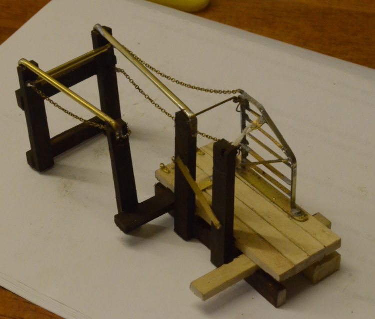
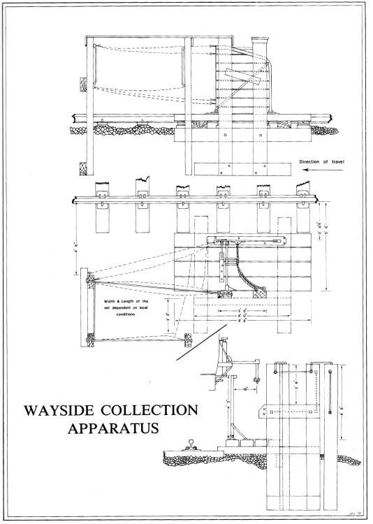
There seems to be a myriad of versions, but the main action is for the rope and bar to catch the bags and have them flung into a net which is supported by the sleepers and bars as shown. The metal frame which is closest to the railside is usually hinged, but I have made mine fixed. The net is at a slant to the railside and access to the bags for the postman is on this side of the framing. Looking at the many drawings available the chains that support the netting is very coarse. Similar to the nets used by quayside cranes to lift crates onto ships.
Well after some thought and discussions at Telford with various folk. Hair netting came up. So I have invested in some, the horsey type that tends to be thicker and stronger. Then while sorting through an electrical box of bits I came across this string bag used to hold computer cables. the two options are shown below.
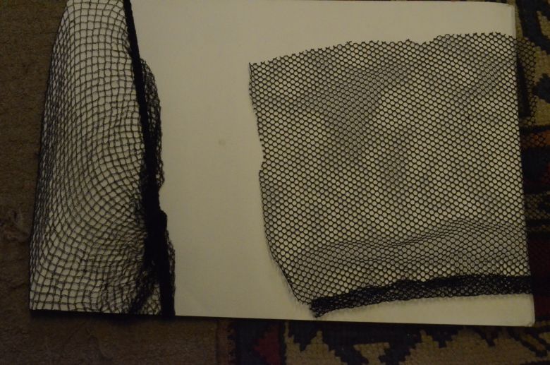
The net on the right is the computer one not woven but looks right and is strong. The one on the left is a rider hairnet. A lot lighter but strong although too flexible.
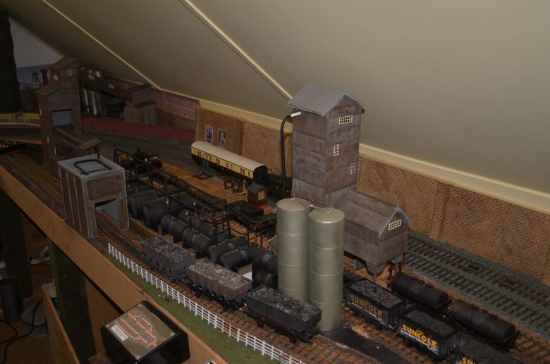
Ok I'll come clean - There isn't enough line side space to fit the catching gear in properly so I will have to make some adjustments to the sidings at the back of the ore works, (see below). This will involve the lifting of track and the realignment of the branch line to the coalmine.
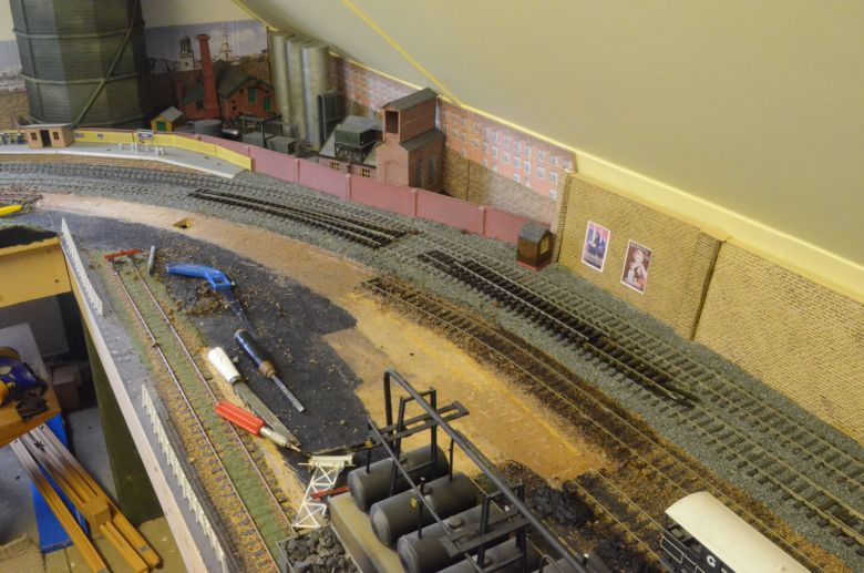
Looking up the track the curved turnout has been removed and will be resited now feeding the lower two tracks. The one closest to the mainline will have a 2' section removed.
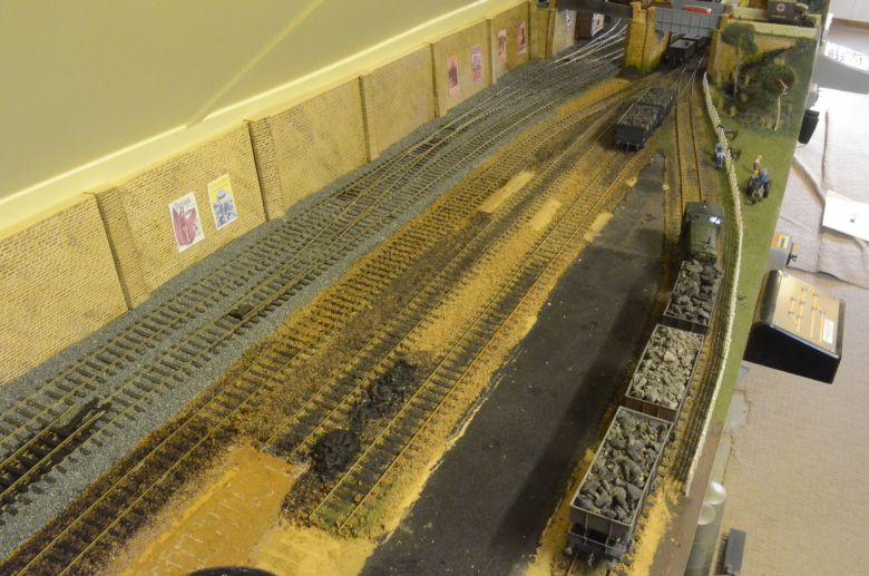
Its a long siding and the long length after removal will leave a shunting spur at the other end. This gap is where the TPO apparatus will now sit.
The ground is now cleared. The curved turnout will be replaced to feed the two remaining tracks as shown here.
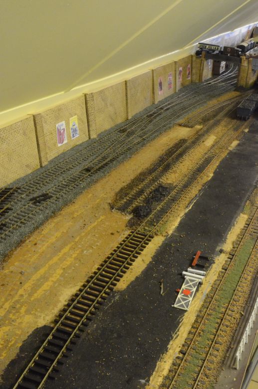
Now I have plenty of space to fit in the ground gear as shown below!
It is now just a matter of realigning the control panel for this section as the siding arrangement has been altered slightly and the tar and coke works buildings will need some modification to make use of two instead of three roads.
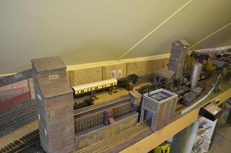
Essentially the tar and coke works had to be redesigned with a couple of alterations to the buildings, (one turned through 180 degrees), but it was of little consequence as shown here:
As stated, the tar tower has been turned through 180' and its platform now juts out to the right instead of the left and because of that I have been able to keep everything else almost the same.
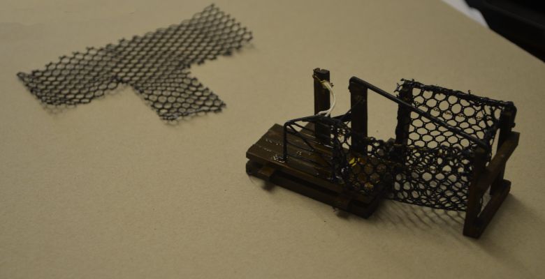
Back to the ground equipment and the netting has been created, not from hairnets as mentioned previously, as this was too flimsy. The image below shows the pattern and final positioning of the net. the 'T' was a first trial but needed an extension on one arm as it has to fit a 'parabolic' type shape. it was glued in position and finally sewed in place to give extra strength. The corners of the net were also glued and sewed.
Thinking about the mailbags, I have used some white metal pigeon baskets and they look the part as shown here:
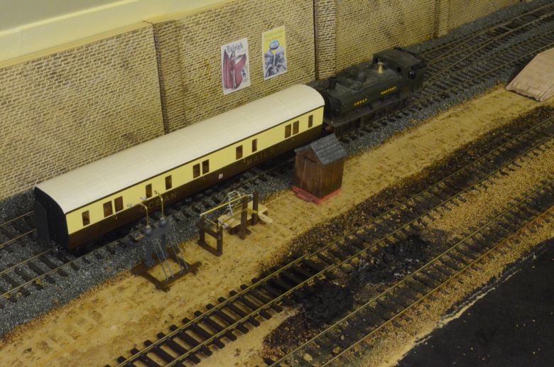
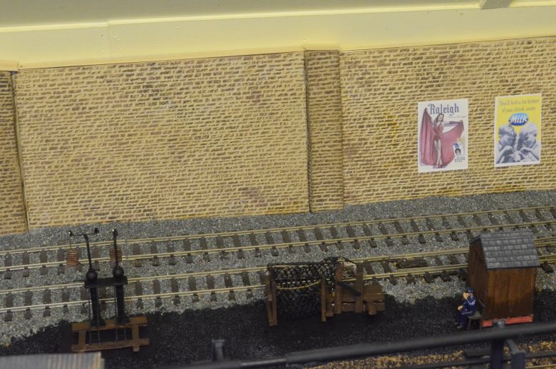
Here is the ground gear insitu The chap waiting outside the postman's box has got a long wait though!
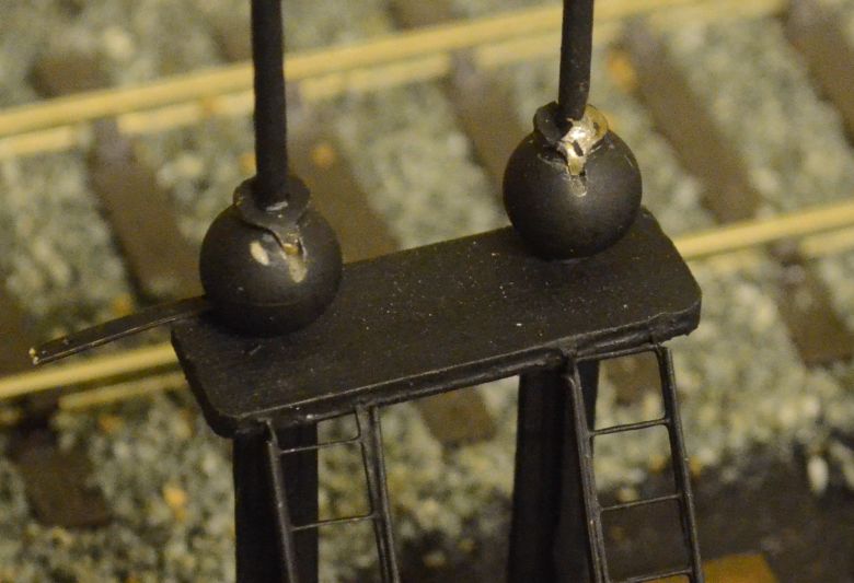
Here is a close-up of the securing slots described earlier in the ground apparatus.
The ground apparatus has been glued in position. After several manual passings of the coach with the gear down to access clearances. This having been done the net and the arm structures are now glued in place. The last piece of ground equipment is a warning sign, (black and yellow squares positioned a little way before the ground apparatus).This will be made up next.
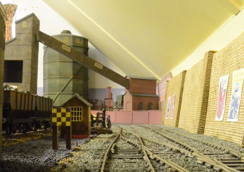
And that completes this section!