O Gauge Modelling on the GWR
A personal Journey
Steam Railmotor
I decided to start on the body of the Steam Railmotor. As a fellow modeller at Reading earlier this year said, "You've got two kits there not just one!" and surely he was right about that. I have just spent some time putting together the body of this Scorpio kit. The instructions are like a lot of others, they don't show you blow by blow what to do so a lot of extra images is necessary, (the numbering and location of parts is not always clear either and the etchings are not marked). However I have got as far as making up most of the body. getting it square and making it a right fit takes a lot of time and some of the etchings need cutting down as they are over size, (although the instructions tells you this). I am going to make a small adjustment to how the roof is connected to the body though as they tell you to use a couple of compartment dividers and tab them into the chassis. I would prefer to have the roof screwed down so that it could be taken apart easily
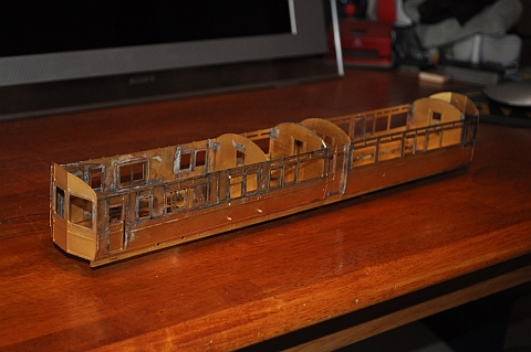 |
This is definitely not a beginners kit. The amount of soldering and skill needed to put things together is beyond the beginner. As the body is so long and the sides come in 4 pieces it needs a careful eye and a lot of patience to get it right. I'm sure that one of the side panels is slightly larger height wise than the other three, but there is not way you can fettle it to make it the same as the other three. this may have occurred as the etchings have to be bent over to give full depth detail. This necessitates careful bending with the same approach being used on all four pieces, (not an easy thing).
One important modification to the design is the strengthening brackets along the top of the sides. I did this partly to strengthen the coach but also to improve the butting of the roof up against the sides. As its such a difficult flexible assembly as far as the roof is concerned. I decided to use 'struts' in the roof and put flanges along the top of the sides. This solved both issues. Unlike the instructions I will be screwing the roof to the body., (they suggest that some of the partitions are fixed to the roof and that is used to 'tab' the roof to the floor, great if you don't intend ever to undo it!).
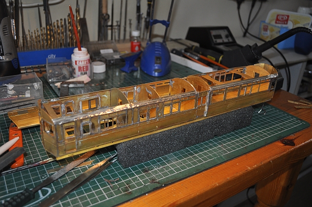 |
Here the roof is resting on top of the carriage. I also put tags on the roof to hold it longitudinally. The drivers door handles are so small that its easy to loose them ala tweezer pinch!
 |
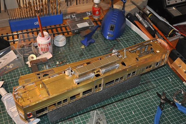
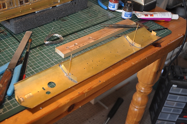
Most of the body and roof is now complete although I haven't yet decided how the roof will be fixed to the body, (it will be screwed though). The interior of the coach needs to be completed but for now I'm concentrating on the underside. The braking gear and control rodding all needs careful handling and from the many bags of bits I did find the correct parts eventually. I have got so far with the rodding but I would want to put the bogies in place first before cutting and connecting up any rods here. I used epoxy to stick the whitemetal tanks in place and the vacuum chambers. their lever systems are soldered in place. A lot of care needed here!!
 |
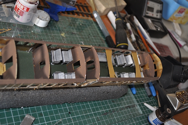
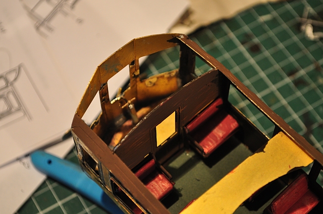
Making up all the seats in white metal took some time and your soldering technique needs to be 'good'. But after the card floor was cut out and inserted it was an easy job to glue them in place. A quick run round with the paintbrush with stock brown to hide the brass walls etc will make it more realistic once the roof is fixed in place.
 |
Whilst thinking about the roof. I decided to make up two struts from brass pipe with a 6 BA bolt soldered on the end of each. This will be used to secure the roof to the floor and tension it against the walls of the coach. If you look at the image above you can just make out the strengthening struts I soldered on top of the walls to give both strength to the body and help hide any light that may show due to the roof and walls not being an exact fit!
 |
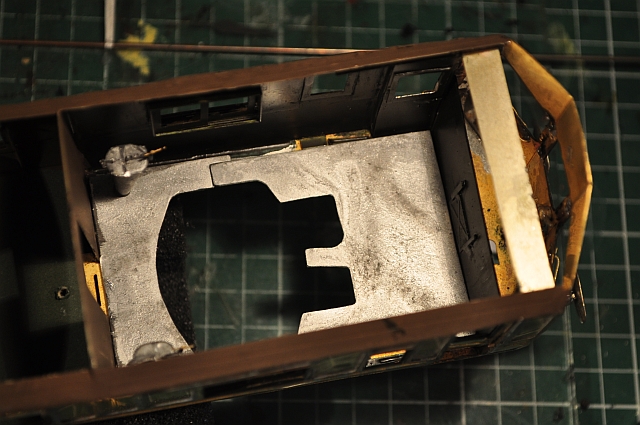
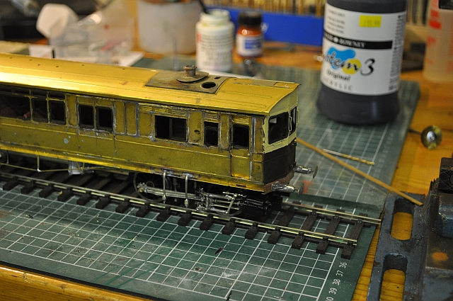
Putting the final touches to the body. First painting the window frames, (there was no cellophane so a 'reccy' in the bits box found some but this will not be put in place until the internal and external painting has been completed). Next the drivers controls at each end. The data here is sketchy to say the least ns a I'm making the Q version, John Lewis's book, ( Great Western Steam Rail motors) is proving very useful. However the kit and the drawings are not the same so some investigation is necessary. Q1 doesn't have certain handles whereas at the Q version does. Also internally, the braking mechanism and controls do differ from the instructions in the kit and the stock drawings, (where is the coal bunker in the kit for instance?), not that you can see these items necessarily. The engine compartment has whitemetal inserts for the floor. My main concern is that nothing is said of them and putting them in place before the motor unit is complete might be a big mistake. However I have tack soldered them in place.
 |
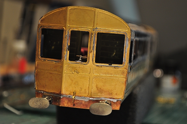
The handle grips at each end have been soldered in place. As mentioned earlier the Q1 does not have a second set beneath those at the bottom of the windows. The lamp holders will have to be glued in place as there is not room to get a soldering iron tip in!
 |
You can just make out the handles fitted here and the lamp holders inserted but not fixed, (that's a relief as they aren't positioned properly). The buffers, I decided, are not sprung but fixed. More detail is to follow but there are no holes in the body for fixing so these will either have to be organised or external detail will be glued on.
 |
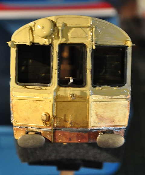
At the risk of being likened to Stan in Dinner ladies, I took the trouble to look into what the back end of a Q steam railmotor looked like. Only to be confronted with a variety of options that included lines painted on the windows or not, windscreen wipers or not. Connecting apparatus being in full working order or successively removed bit by bit. So I have trudged the middle road, (message to all the Stans out there - don't bother to offer informed help it will fall on deaf ears and life's too short etc, ). So here it is unpainted.
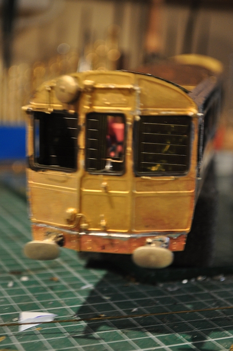 |
Here it is with the first coat of cream paint. I'll have to go over
the brown frames again as the pipework makes it near impossible not to
touch those parts etc....
Locating the correct bits in the kit is an adventure in itself. the
parts are only numbered in the text images but the numbering is not
consistent as duplicate numbers crop up in both the engine and body
sections. Also some are not numbered at all and are hidden on sprue
somewhere!!
 |
Putting the body to one side its now time to start on the bogies. First the trailing bogie. compared to the other end relatively unsophisticated! But fiddly non the less. The brake detail will have to be left till the end as it will need to be modified so that the bogies can accommodate the 6ft curves.
 |
The real challenge comes with the construction of the motorised bogie. A good level of soldering skill is needed to prepare the items for assembly. The instructions seem to flit backwards and forwards so that some important information needed at one point is not mentioned till much later so good scrutiny of them is required. Here I have reached the stage where the basic con rods and slidebars are in place. The system is still a little stiff and this is not easy to get rid of so some tweaking will be necessary
 |
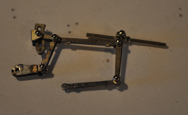
The valve gear assembly is somewhat complicated in that many of the pieces have forks at one or both ends some of which are offset to the connecting laminate. Yes they are also laminated. Only one fork proved to be a problem and broke off. I substituted a piece from the sprue! Now they are to be connected together and fitted to the bogie.
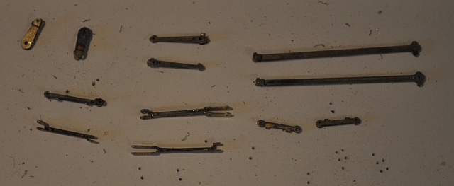 |
Here is the left hand side of the valve gear connected. The method of using pins soldered to the backs of the plates needs a lot of care. In spite of the way they are put together the structure is still quite fragile. The thicknesses of the reversing gear leverage was far too thick so I had to modify it by removing the flanges and filling and drilling a small hole to pivot it in the chassis frame.
 |
The valve gear in position and yet to be anchored in place. The valve gear pivots about two chassis supports and this needs to be checked for free movement otherwise all will end in tears! This has taken about 8 hours to get to this stage. The eccentrics need to be 'set' but there seems to be issues with the draw rods and clearances which I will need to come back to at a later date. For now it holds together and I need to roll the boiler and its several component pieces. This I do with the aid of a nylon roller and a soft cloth several layers thick on the floor. Applying rolling pressure carefully bends the boiler sections while sinking into the layers of fabric to nearly the required shape. It takes quite a time but is good exercise!
 |
| Well the sand boxes have now been fitted, you can see them end on
still in unpainted state. The instructions are a bit sketchy on how and
where they fit etc so John Lewis's book Great Western Steam Railmotors
is a boon here. Also for the boiler fittings as the pictures in the
instructions made me think I was sight impaired at times! Remember most
of this detail is going to be hidden inside the cab, but we'll all know
its there won't we? |
 |
 |
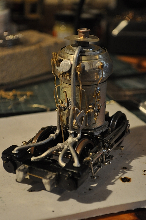
More detail on the boiler. Nearing completion of the fiddly bits.
What puzzles me though is the cowling on the chimney. It appears above
the roof in reality but would need to be completed after the boiler and
chassis is in situ. Painted the boiler polished steel and the exhaust
pipes black then a light covering of rust. Good old Slaters wheels have rusted themselves up nicely by this time so a mini drill and brass brush will be needed to clean them up. |
 Interestingly the pivot brackets for the support are only mentioned at this time as, (you already have fitted - really!). Not so of course as they are given no mention until now. Anyway the requisite holes were drilled using the drawings from the Railmotor book and the hangers fitted. You can just see the hangers on this side underneath the con rods. The amount of clearance is minimal both for the motor gearing and the con rod so careful adjustments may be necessary. My main concern now is that the amount of turn required by the bogie once on the tracks will not be achievable in its present form. I will need to investigate an alternative method of securing this motorised bogie to the chassis! To this end I made up a pivot that connects with the motor bracket and the subframe of the coach. It has two pivot points so should give a fair amount of slop for the curves. The outside supports were cut off but their bushes left to make it look like they were intact. Also had to solder extra brass plate to give wider clearance of the supports so they wouldn't foul the gear on the curves. |
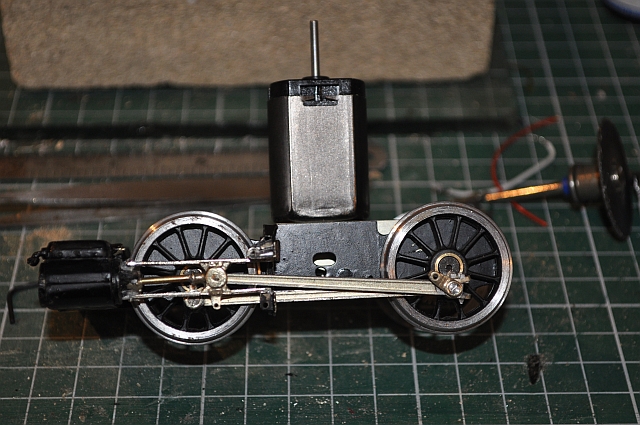
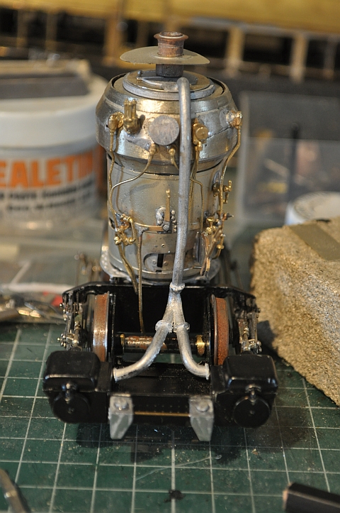
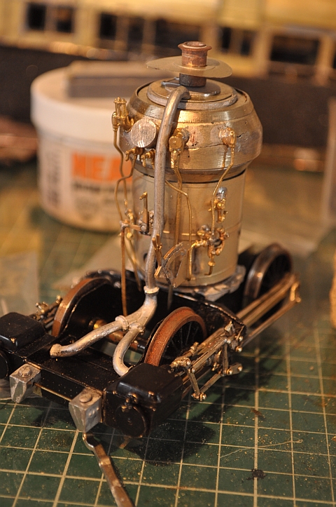
 Here is a mock-up of the two parts, Motor and body). Sure enough how this can negotiate a curve of any sort in its present state is any bodies guess! I will need to realign the method of connection of the motor to the body as there are literally no clearances as it stands. Also the reversing gear and connecting rod need to be fixed somehow as they tend to slip and jam the outside cylinder gearing. but apart from that its taking shape. A point that always mystifies me is why so much attention to detail on the boiler when its mostly hidden from view and can hardly bee seen when painted, (very much like break gear). As mentioned previously the metal inserts for the floor have been discarded so that the complete motorised unit including boiler can be offered up into the body. The chimney and cowling are now correctly positioned outside the roof instead of under it and this adds to the stability of the whole thing. |
 Good news. it has been put together and given its first run. Needs running in but it moves forwards and backwards satisfactorily. Had to make some major changes to the front gearing and remove the method of supporting the motor at the front end. At the cost of authentic supports they were cut back so that the front end could swivel under the body. You can't tell what I've done to achieve that so in my book its acceptable. Its noisy, heavy and cumbersome but its working! Now the brake arrangement needs finishing off and painting can commence, (again some of the cables will have to be rerouted as this model will traverse my 12ft curves). As its to run on a DCC layout I will also have to organise installing that but not for now. |
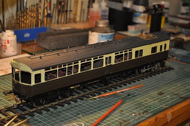 Now in the paint shop. The roof has had three coats of paint and the sides have had their initial base coats applied thickly. The next coats will be applied very carefully specially around the windows. The vehicle will be numbered 30 and have the dual coat of arms and GWR on the sides afterwards. Glazing will take place as a last item on this model. Taking it apart is a three step process as the front bogie is suspended differently to the instructions and the rear bogie provides stability. |
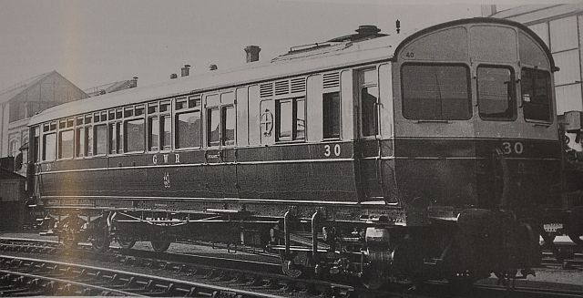 Here is a picture of the original. As there were so many variations even with paint jobs on each motor. I've chosen the easiest cream and brown version to copy |
|
This is the real thing in service. An amazing achievement by the Didcot folk and one of a kind. Mine is cream and brown though! |
|
And this is a video of my finished project |
GWR Steam Railmotor
Several projects rolled into one!