O Gauge Modelling on the GWR
A personal Journey
GWR HYDRA
This is how the kit comes in a plastic bag from Connoisseur Models. The wheels are extra as are transfers.
Click on each image for a larger view.
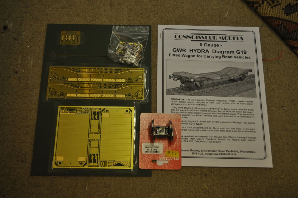
This is called a 'skill builder' model which means its fairly straight forward to build. The instructions have Jim's usual thoughts on soldering etc and then follows 8 pages to help you to build it. The images on these pages are large and clear and include photos of the finished but not painted model.
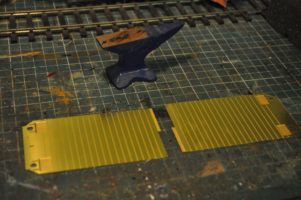
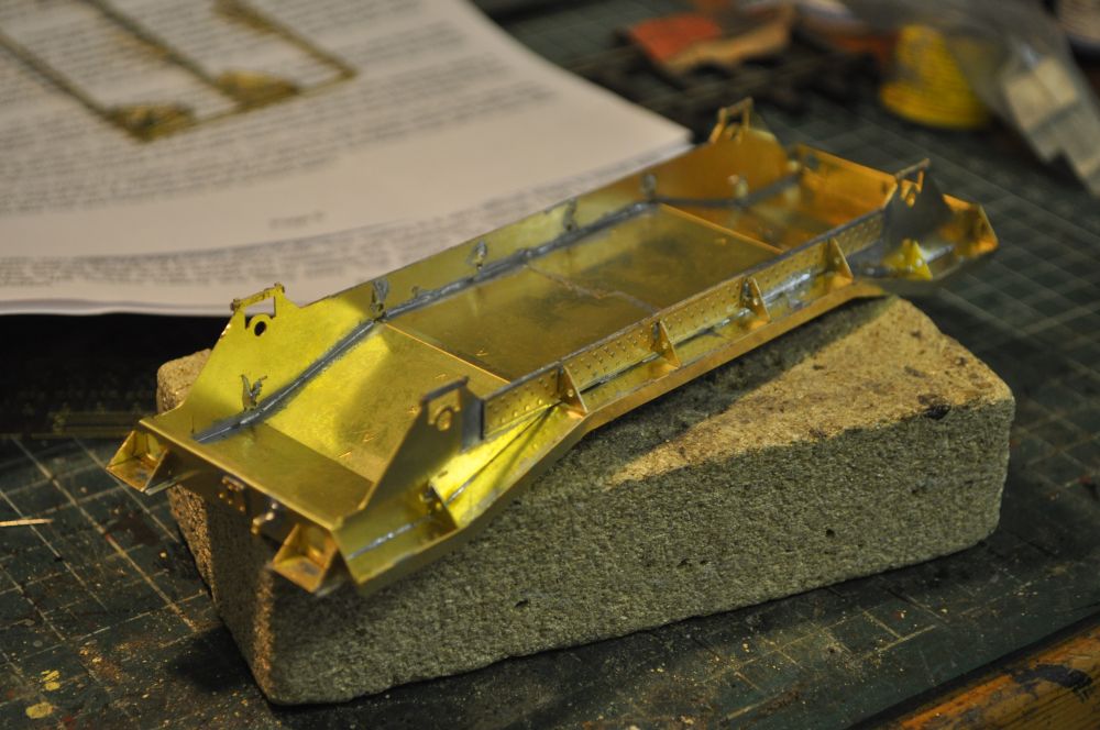
You start by cutting out the floor, (which is in two pieces), from the fret. Great care is needed as the tabs that hold both pieces together are very very thin and liable to warping when cut out. I used a small anvil to flatten the tabs after freeing them from the fret. i used a sharp knife and cutters either left marks that needed flattening. the Dremel ground the sprue away easily. here they are ready for soldering togther.
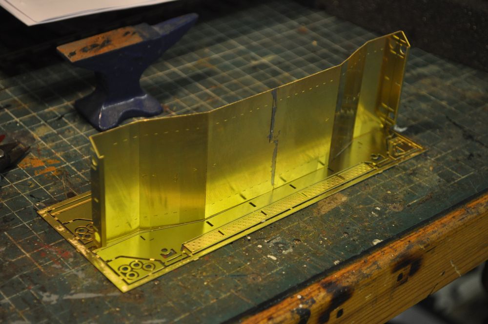
The floor is folded using the sides as a guide. As the floor is slatted it will bend easily therefore care is needed in getting it to bend in the right places. fortunately, the folds are such that this becomes easy as the top folds are on the slat lines and the bottom folds are clearly marked underneath the floor. I used long nosed pliers, Jim suggests alternatives.
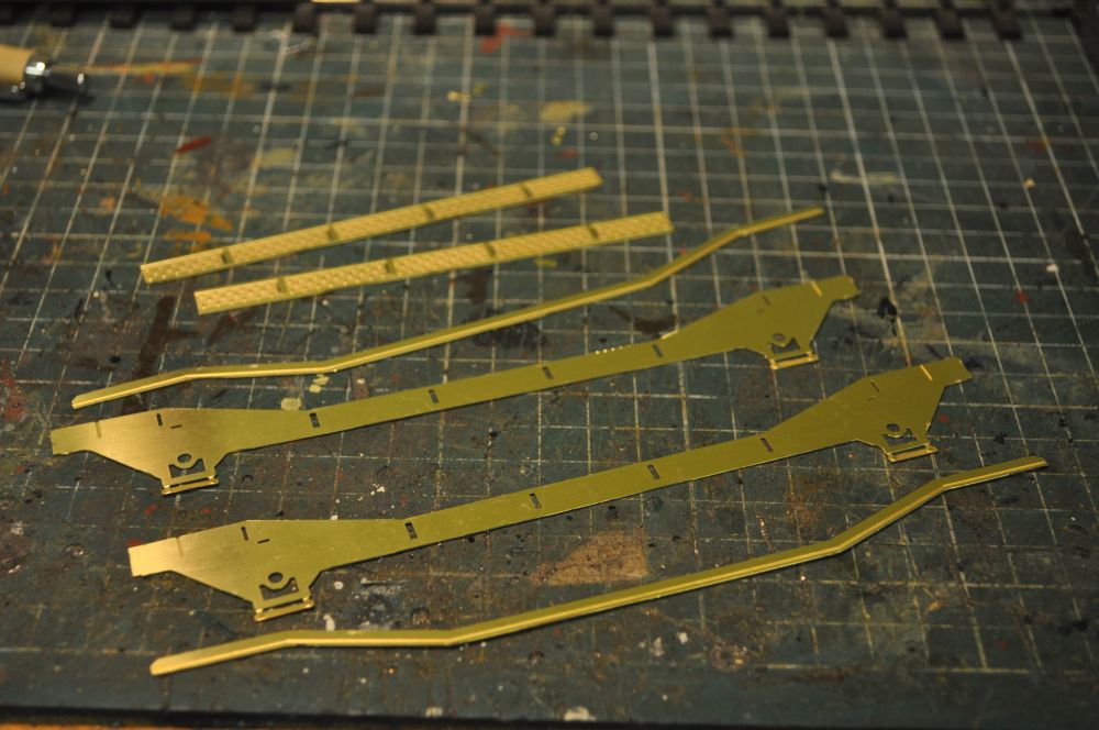
Cut out the side plates, axle box keeper plates, rivet detail overlays and the curb rails and tidy up with the Dremel. Use a knife to carefully separate each piece from the fret.
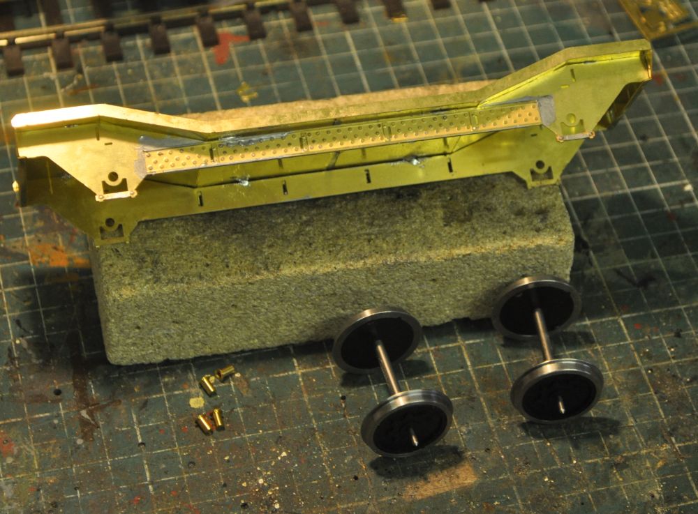
After soldering up the axle box keeper plates and laminating the side plates and fitting the curb rails the side plates can be tack soldered in place to allow for the fitting of the wheels.
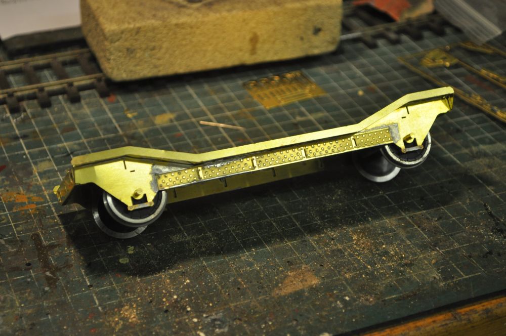
The sides have now been soldered in properly and the wheels fitted. Next job is to fit the triangular bracing plates. You can see the slots for these. One thing to be aware of here is that flux contaminates all surfaces and if corrosive will rust metal surfaces quickly. this can be a particular problem with Slaters wheels. Covering them in Vaseline helps but frequent washing with flash liquid removes any flux that might be lurking in the odd corner etc.
In fact to complete the next few stages its easier to remove the wheels. The side fillets can then be soldered in place particularly the ones that would be masked by the wheels are now accessible. Also the end loading plates and their support brackets can be fitted. along with the coupling plates and lamp brackets on the buffer beams.
Brake 'V' hangers were soldered into place up against the buffer beams on the inside of the side plates. Then fold and laminate the brake blocks onto the brake hangers and fit them onto place with the wheels still removed. I'm replacing the buffers with spring ones. So they are ordered more on them when they arrive. The screw cou0plings are next made up. Unfortunately the white metal joints are weak and will break easily so I'm making up my own with a combination of brass wire and the couplings provided. Now is the time to put the wheels back, check that the brake shoes are not fowling the wheels and glue on the axle boxes.
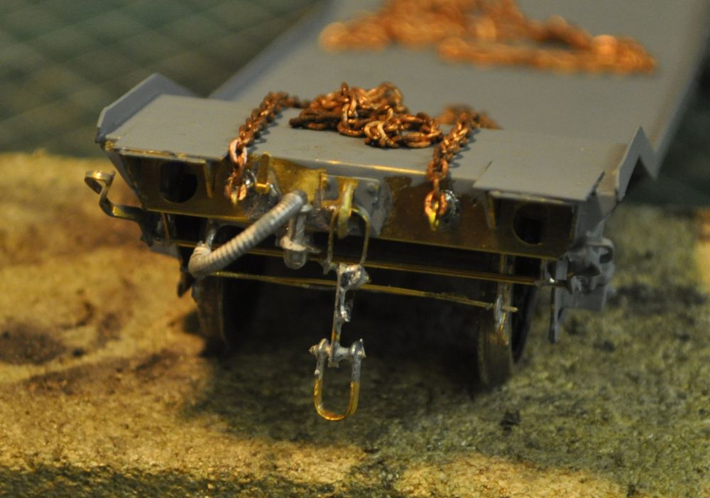
Whilst waiting for the buffers to arrive, I investigated how chains might be secured to the hydra. It seems that some early Lowmacs had the chains secured on the buffer beams and so I have incorporated hooks as shown here at both ends. You can also see my efforts at making the coupling gear and although a little too heavy on the solder once painted they will look the part.
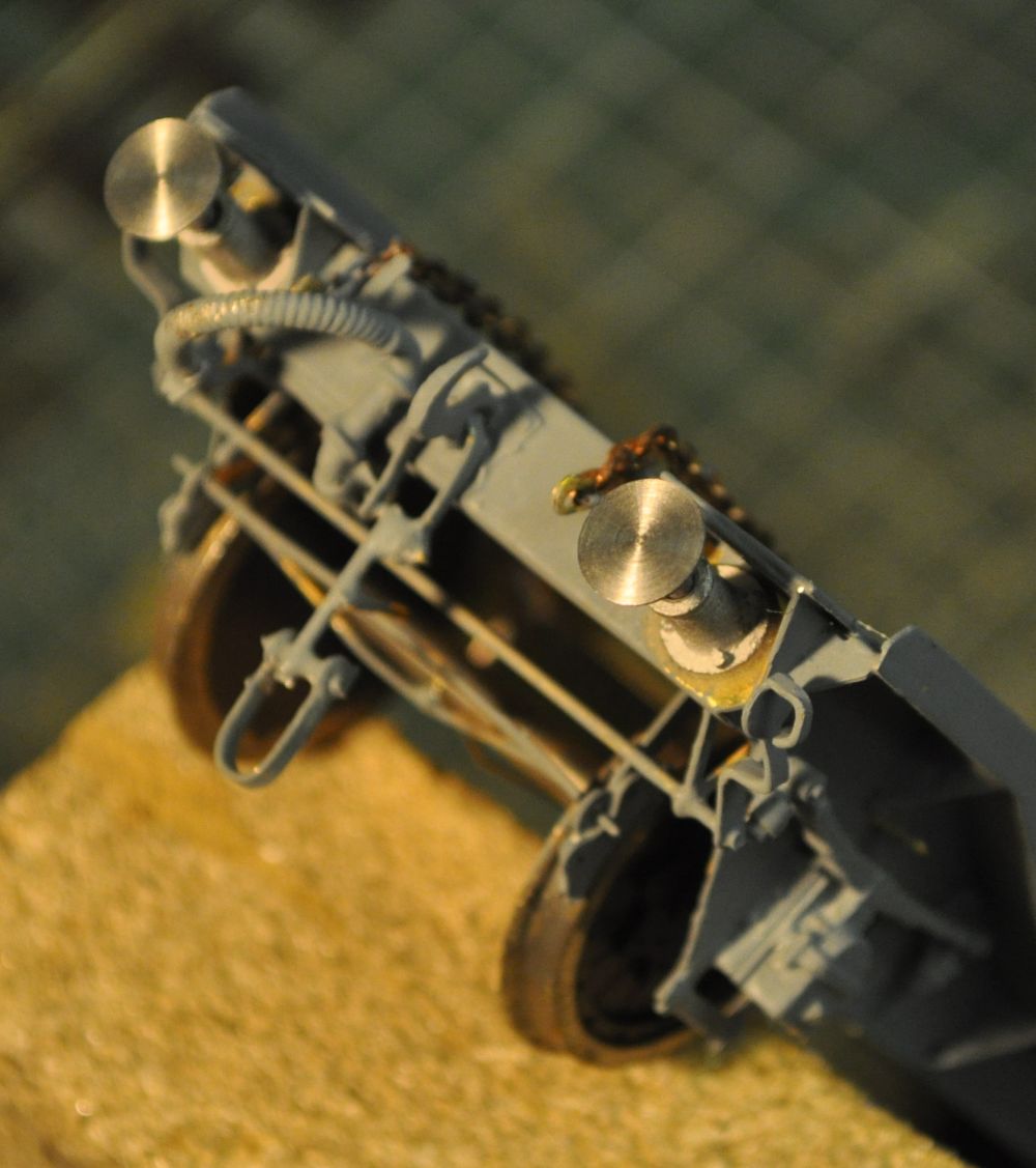
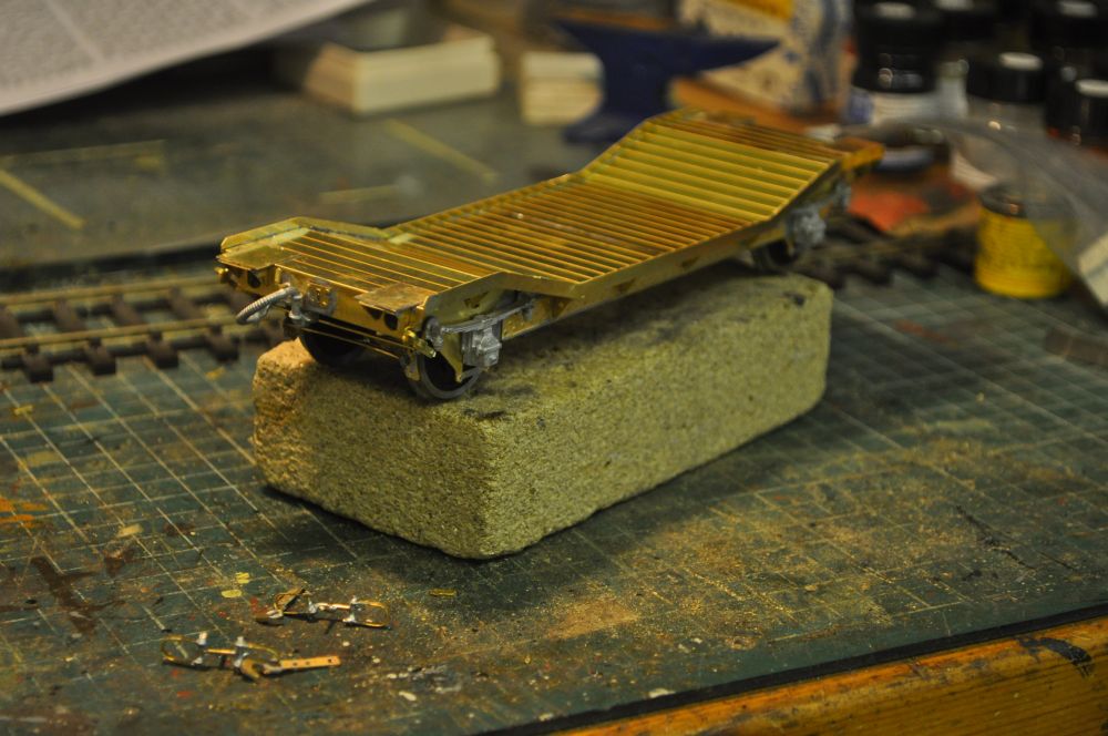
Here are the buffers insitu. A much better offering for £6.75 than those in the kit you have to drill out. Jim even suggests that because of tight space they should be fixed not sprung, but this way you achieve what is correct. Having forgotten to fix in the spring stops, (there are slots to remind you about these), I glued mine in after cutting them down slightly.
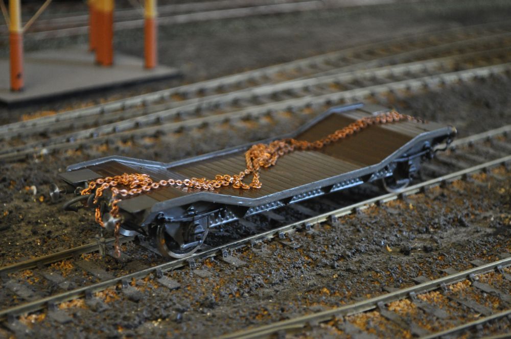
Here is the finished article, (minus decals and lettering etc).