O Gauge Modelling on the GWR
A personal Journey
CONNOISSEUR MODELS LMS Milk Van
All the kits come within an A4 plastic bag. Except for wheels which you purchase separately. here is what it looks like for starters: Click the images for a larger view.
 |
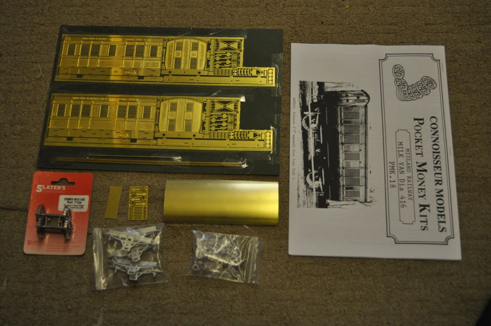 |
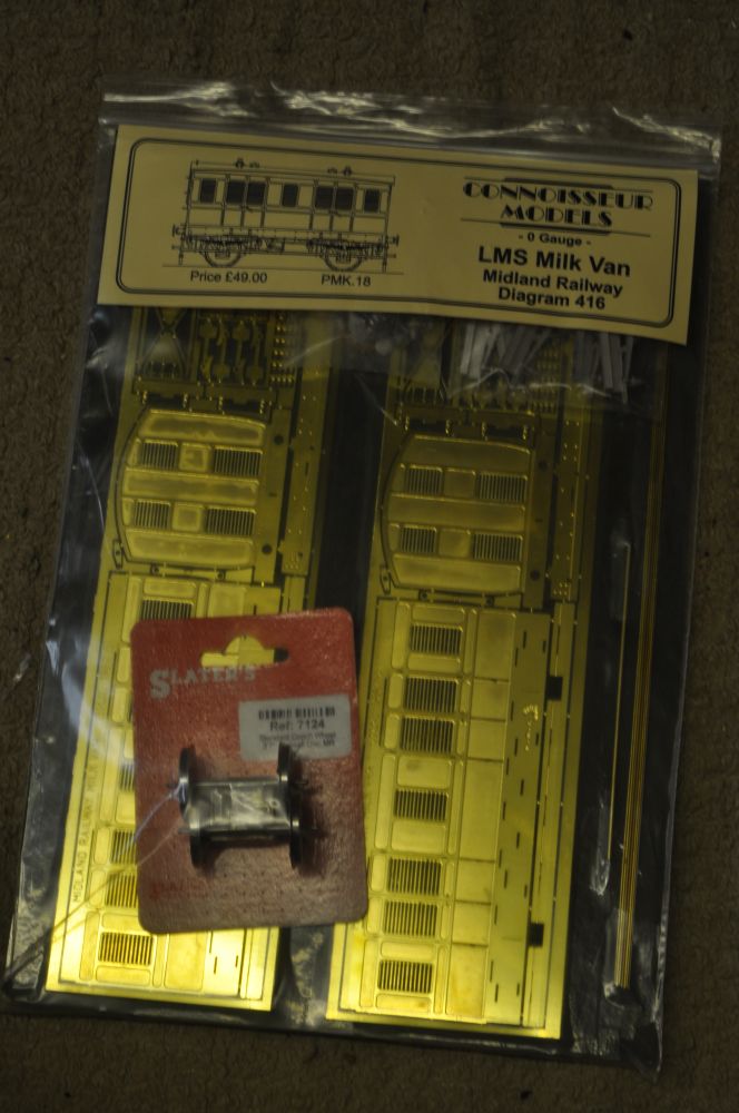
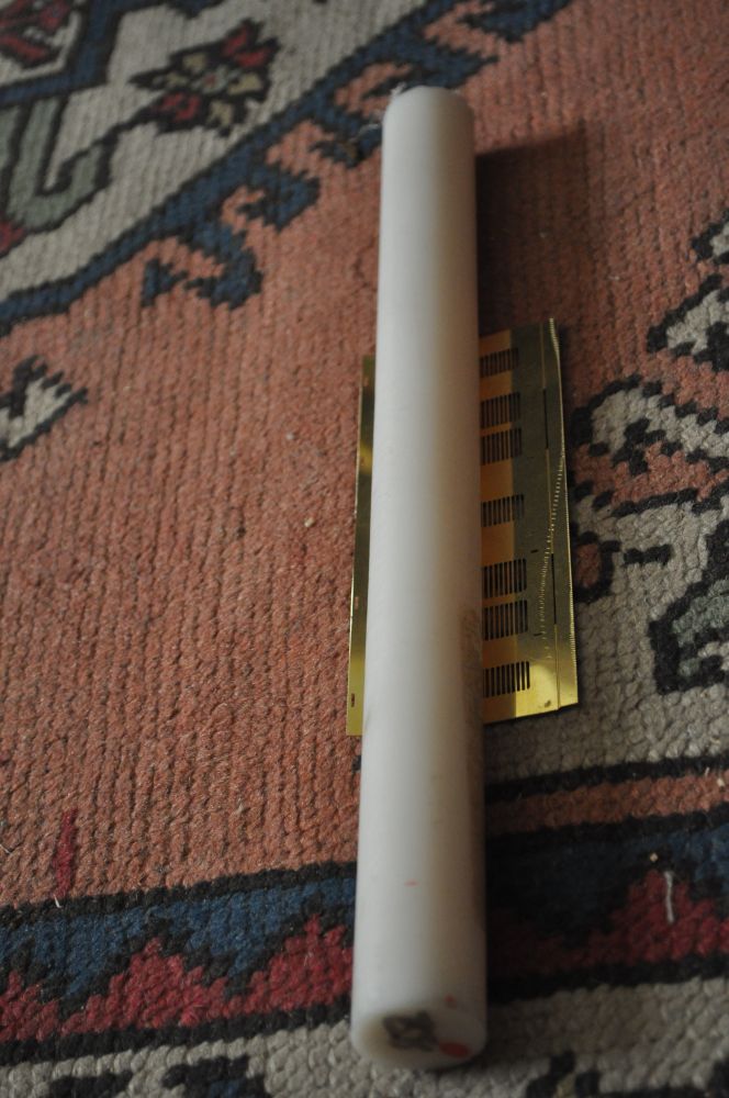
This is what the unopened kit looks like. All Jim's kits are similar. I bought the wheels to go with the kit. The second picture shows the component parts and instructions.
The instructions start by going over soldering basics, this makes this kit a good starter kit for those starting out with an etched kit. He covers laminating and similar techniques and even how best to cut parts from the fret. What then follows is a series of diagrams and close-ups and a list of parts and the assembly order to make up the model.
 |
 |
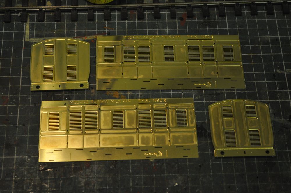
First cut out the sides and ends from the fret. I use a Dremmel with a grinding disc to remove the fret tags from each piece. There are several rivets to emboss at the bottom of each end and I use a special riveting tool for this. The ends can then be folded to make up the buffer beam. The sides now need to be curved to match the ends, this is known as the tumblehome.
| To form the curves that are referred to as the tumblehome, I use a nylon roller, (I have several of differing diameters), and roll it on the carpet. This works for me as I have three layers of carpet on the floor of my workshop, (don't ask!), and this provides a cushioning effect when I press down on the roller and roll it over the necessary area. Its a little hit and miss but works 99% of the time and gives an acceptable result. Its important to keep everything square and provide equal pressure over the roller. Its good to practice! |
 |
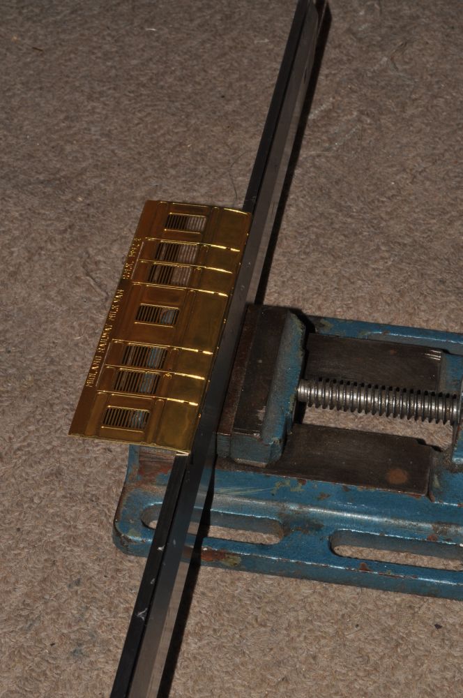 |
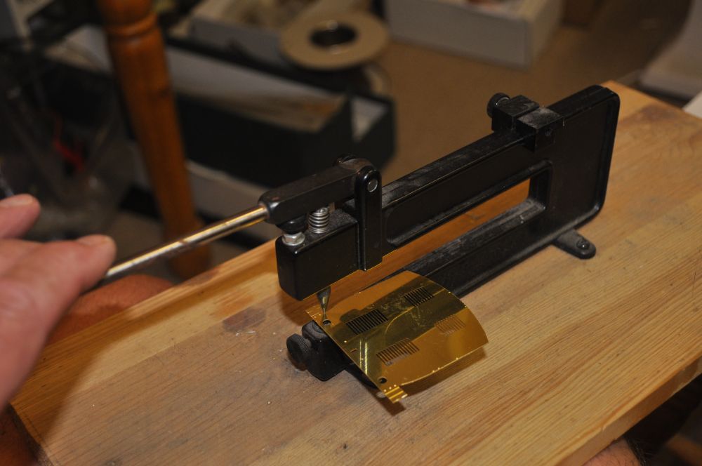
To bend the top and bottom parts of the sides, I use my
bending bars. these are heavy pieces of bright steel with a
chamfered edge. I use one chamfer up the other down and this
gives a fine base to bend most items. I carefully adjust the
pieces so that bending is easy, if it isn't then you are too
close to the bend and it needs to be adjusted. Using my
fingers i carefully bend over the flaps taking care not to
'effect' the tumblehome. The bars are held in a clamp as shown. |
| The end steps are needed at one end only. Seven are required and need also to be riveted and have their ends bent at 90'. These will then be soldered onto one of the end pieces. The diagrams show what and where they must go. |
 |
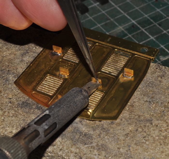 |
The end steps need riveting and then folding. i use pliers for small bends such as this. The rivet flap now needs tinning and can then be soldered to the end plate as shown here. Finally the coupling plates need to be soldered to the centre of the buffer beams in a similar fashion to the steps. |
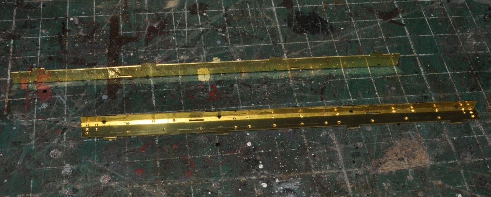
| The sole bars need riveting and then folding 90' using the same techniques as above. Here they are ready to be soldered to the sides. Slots in the sides make it easy to fit the two together, (a real boon if you are a beginner). |
 |
 |
Here are the solebars soldered to the sides. The slotting makes it easy. Its just necessary to be careful and get them square. Also it may be necessary to 'fettle' the ends of the buffer beams so they fit into the solebar. This can be tested at this stage and also make a check to make sure the tumblehome hasn't been altered during the soldering process. I also bent the lower steps at the same time ready for soldering on their supports. |
| In making up the supports for the lower steps I made the supporting bars with a the 90' fold. Each bar was 2.5cm and soldered to the back of the foot boards. there are slots to show where these should be. This makes it easy to solder the supports to the the solbars and hopefully after checking with the axle supports, they will be at the right height! |
 |
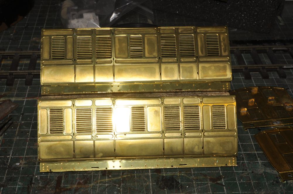
| Now the lower and upper footboards are soldered onto the sides. The sole bars have holes to help you line up the supports for the lower foot boards. This makes up into a strong side. |
| Although the instructions don't mention it now is a good time to put the sides and ends together. Tack solder them in place first. Make sure the body is square and then run a fillet of solder along the inside corners to complete the joints. |
 |
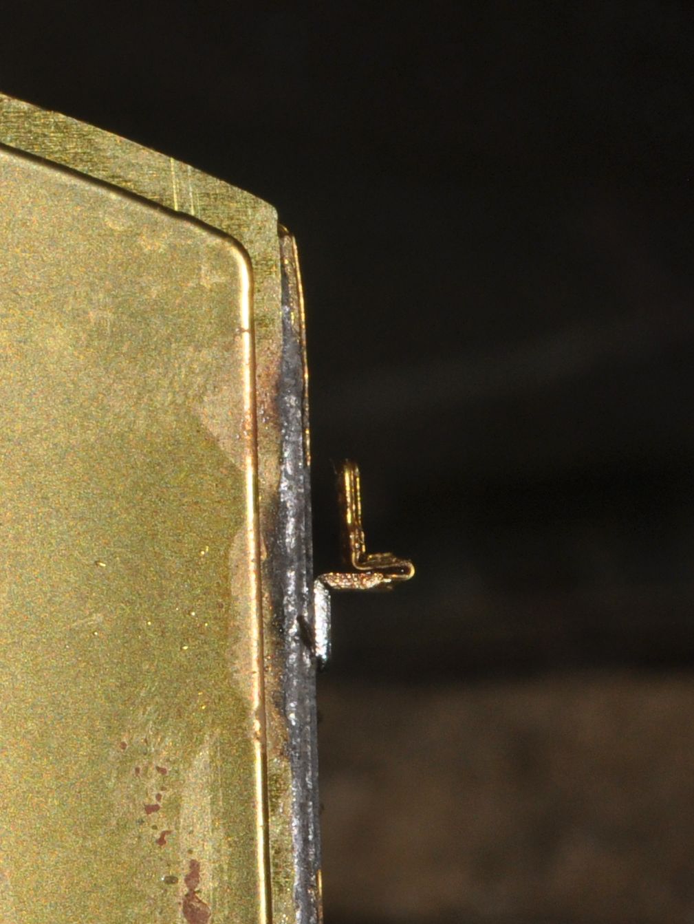
This is the trickiest part thus far and one I left until
now. Fixing the door hinges. The good news is you get more
than you need so this helps if you loose some! I cut out the hinges from the sprue and left the sprue bits on each one to help them 'dangle' in their hole without support, (this worked most of the time!). I chose to dab flux on the hinge holes then insert the hinges from the inside and solder them in place. It seems as if they could be bent over to form double thick hinges but I left them single and snipped off the excess on the outside. Its such a small detail that I didn't think it would matter to the finished painted article. There are 12 to put in place on each side so patience is required here. |
 |
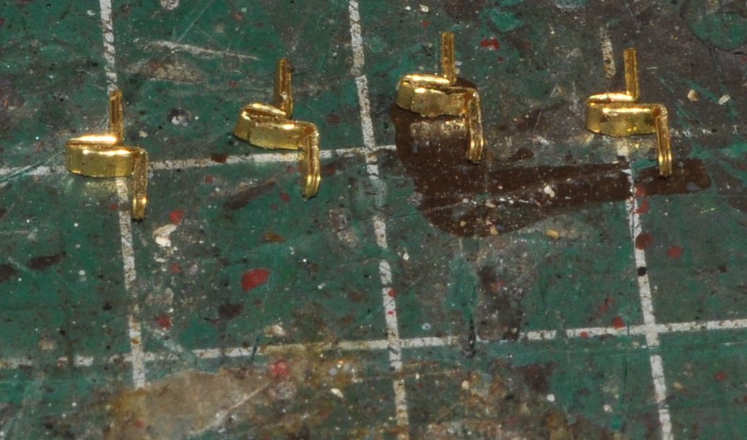 |
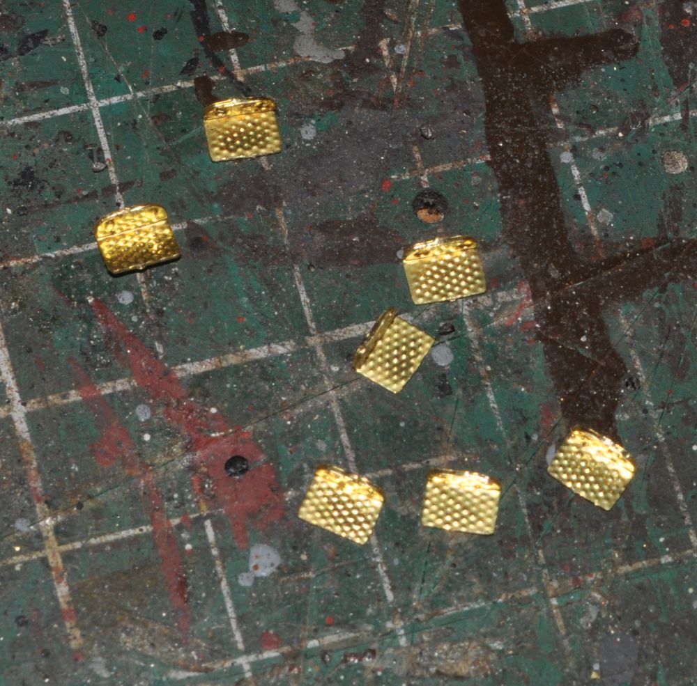
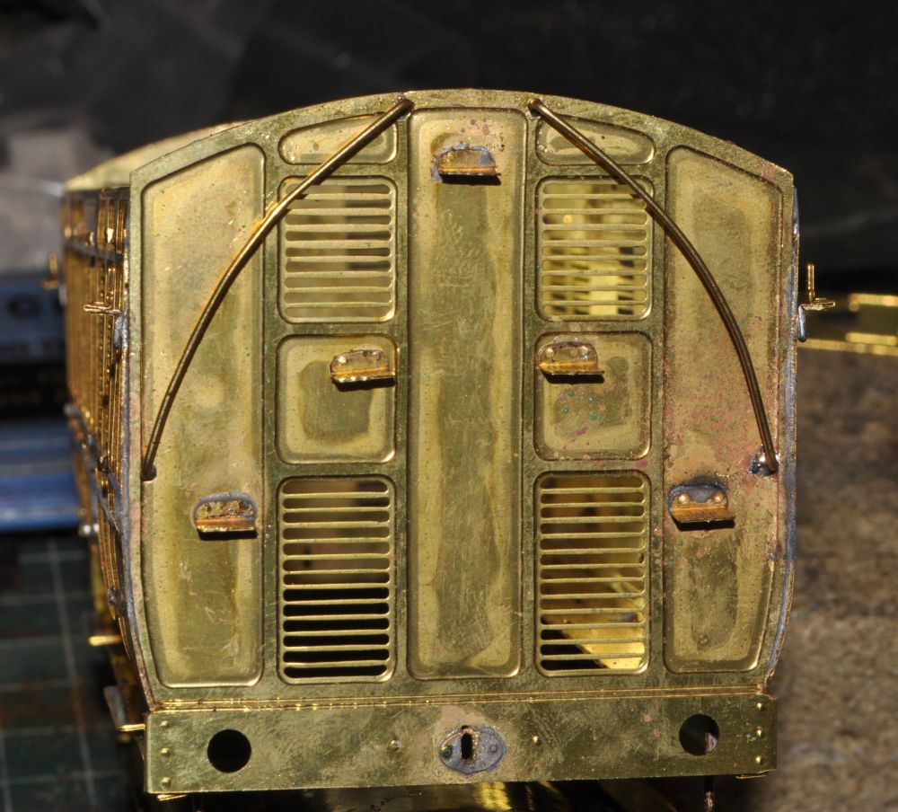
You need to make up 4 lamp brackets next. Bent as above and then soldered in place as shown, one on each corner of the van body.
| The next job is to fix the grab rails in place. The holes will need drilling and I should have done these before putting the body together, but its still not a difficult job to get the holes in the right place at this stage. the rails are then made up from wire and soldered in place. I've also made up a floor from 5mm board and painted it brown. It will be fitted later as the body will need to be cleaned with Flash cleaner to remove the flux residue. |
 |
 |
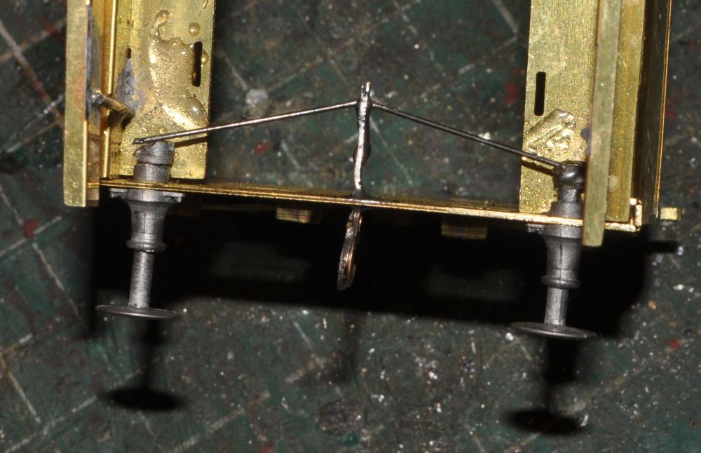 |
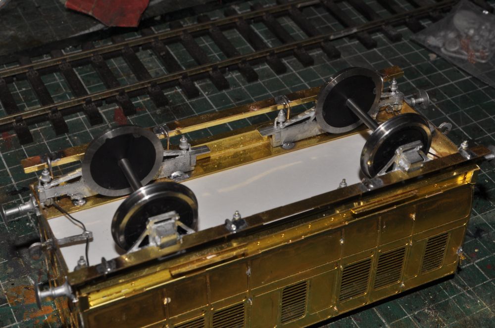
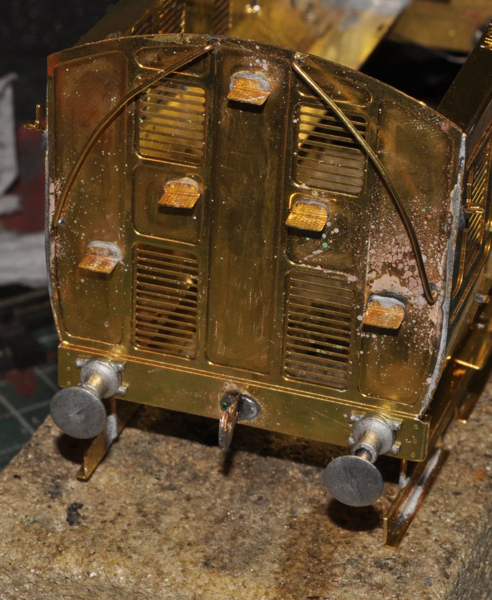
The buffers are made up as per the diagrams. The bores need drilling out and the holes in the buffer beams will need reaming. I glued the buffer housings in with superglue. Put together the laminated coupling hooks and used the spring wire to connect the three together. A bit fiddly but works well once all is in place. Luckily i had extra buffer shafts and spigots in case of disasters!
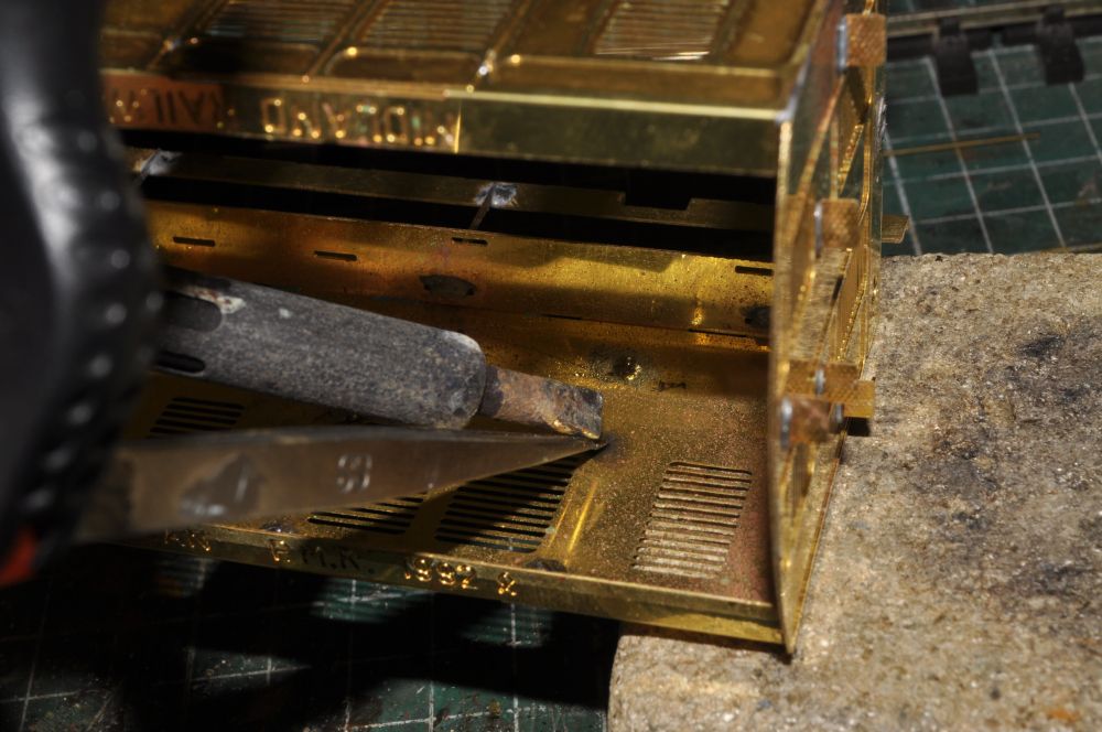
| The axle guards are now drilled out to receive the bearings for the wheels and also an amount of the whitemetal at the outside ends will need removing to allow the buffers to work correctly, (see image 7th above). Once they fit tack solder them into position and check for wheel squareness and level before soldering in place. |
 |
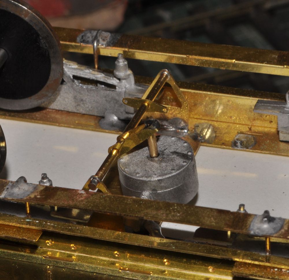 |
Now its time to add detail beneath the body. first to go in is the vacuum chamber. Use a piece of brass offset to the wheels and make up as per the instructions. I replaced the white metal bar that comes out of the chamber with a piece of brass as it is prone to fracture and is not easy to solder in place. |
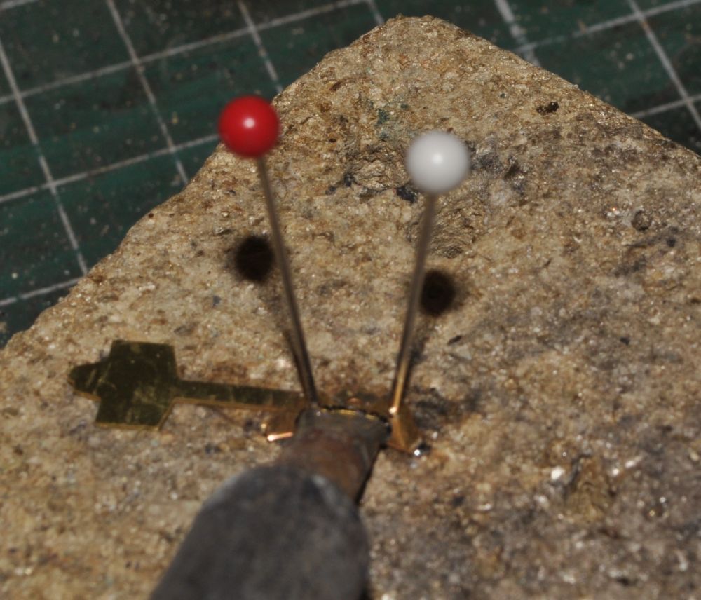
| To solder the brake shoes to the struts use the tried
and tested method of pinning. It works for multilayered
items. Tin one side apply flux and press down with the iron
whilst the pins stop any movement and maintain alignment. |
 |
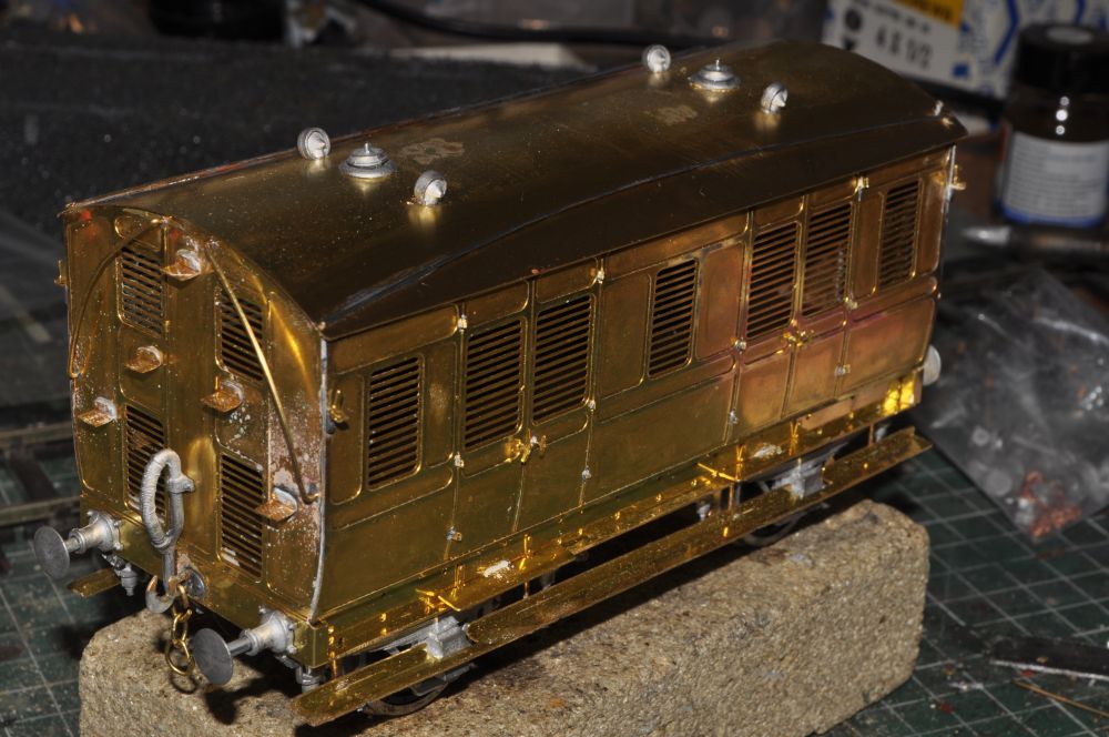
To finish off the brake equipment and cables need to be fitted and the roof drilled to accept the various vents. Finally the roof is stuck in place with Bostik. Now the body is made ready for 2 coats of undercoat.
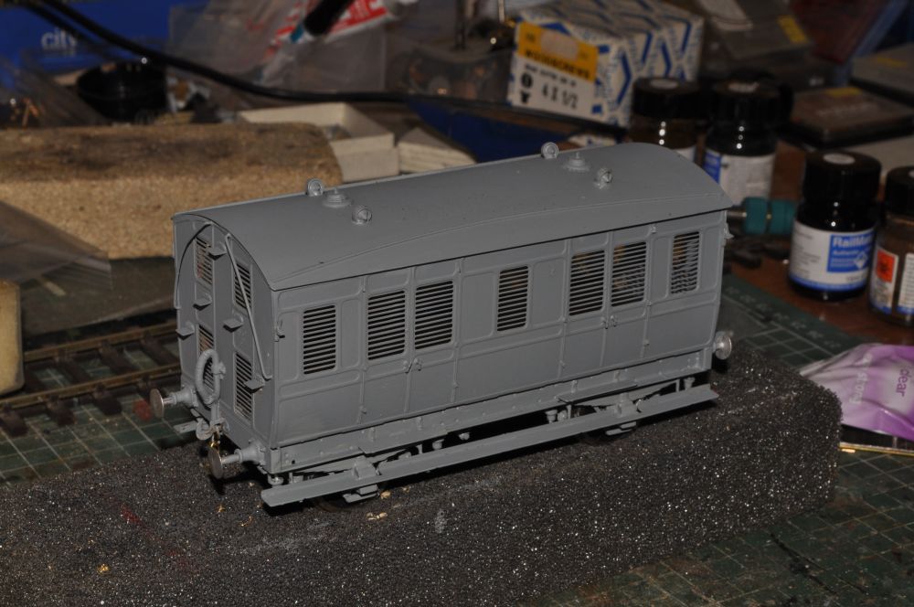
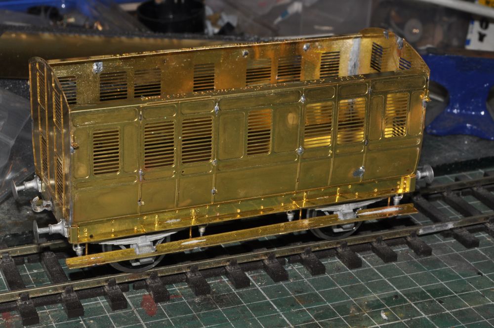
When you put on the first coats of paint the fact that its a brass model disappears, but it starts to take on a personality! Often minute detail is lost and imagery and impression takes over. This is important because modelling is really all about creating an image and the component parts of modelling come together to create a 'picture'.
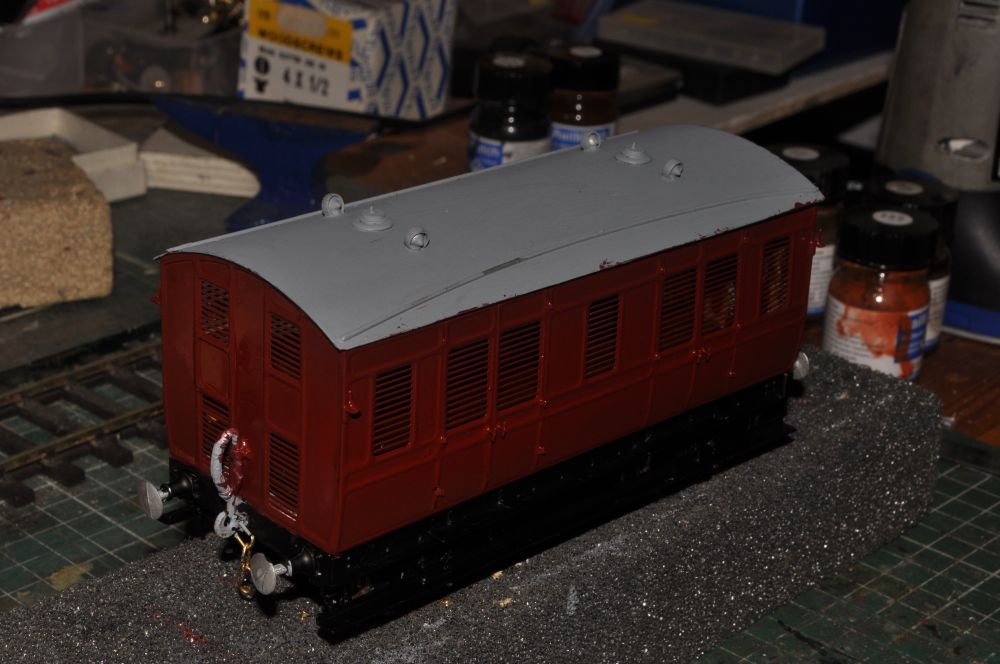
Two coats of Indian Red and matt black on the running gear etc later and it now looks like this.
I've now seen several versions of this van and it appears that lining would be appropriate. Therefore I've purchased a couple of lining pens, (something I've never attempted before), and this seems like a good example to make a start on. The paint now needs a couple of days to dry off properly and harden. I use Railmatch paints.
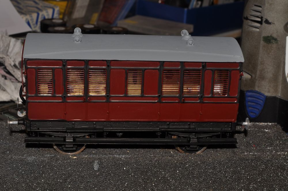
Two days later i am about to start lining the body. I have lining pens on order but have started on the black area on the upper sides of the coach body using a very fine brush.
Yes I have tried lining, but the results after three sessions was too clumsy. I'm not sure if it is me or the etch that won't behave but I have decided to repaint the body. It also looks unrealistic on my layout in its current maroon so the body is going to be freight brown and plain. I will tackle lining again though on another model in the future.