My O Gauge Journal on
Modelling the GWR
A personal Journey
4 way Gantry Project
At the other end of the layout is a four road siding which will be split as two roads for carriage storage and 2 roads for engine storage and house an engine shed. the two lines will be isolated to hold up to 4 locomotives on these two lines.
To facilitate this I will need to create a gantry out of two junction colour light signals and a single signal. In a previous project only one 3 way signal was used and was made up of a junction signal and a single 2 aspect signal.
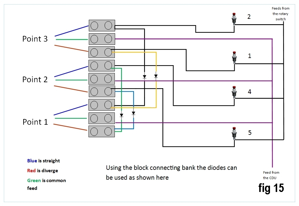
Here is the circuit diagram needed to control all of this using a single rotary switch. Click it for an enlarged view.
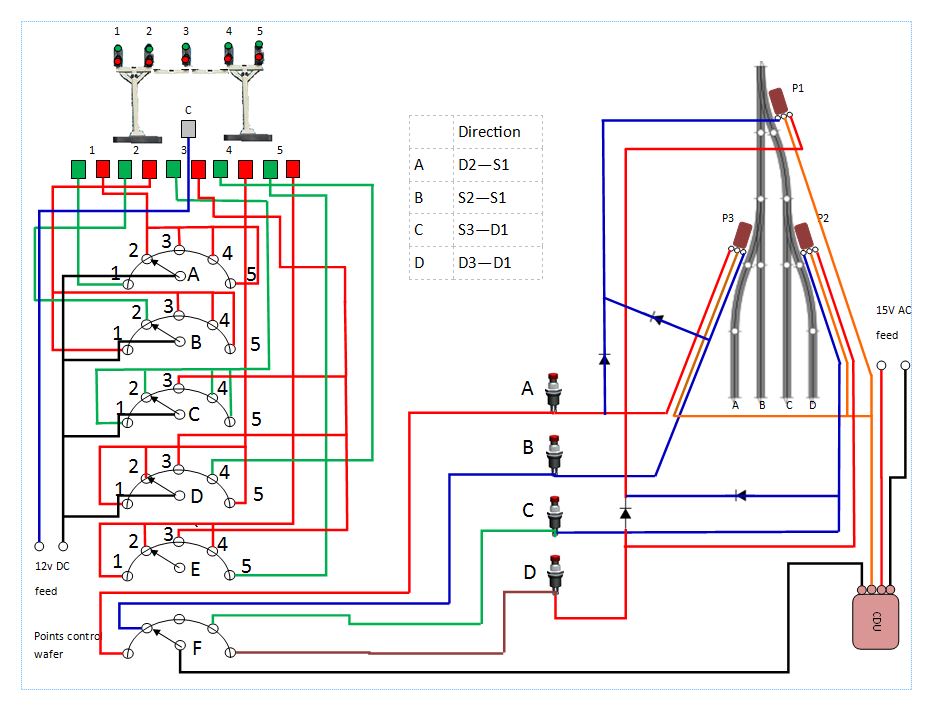
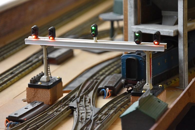
The gantry was made up as follows:
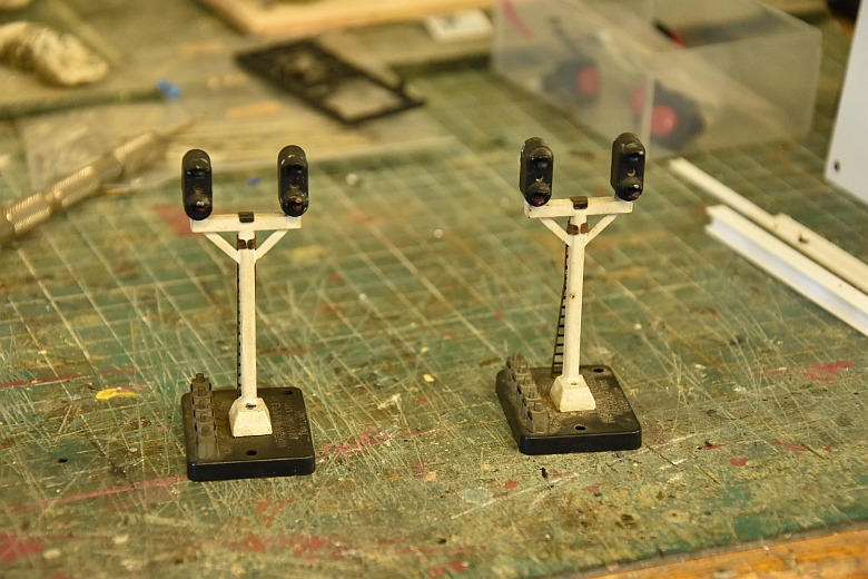
Two junction signals, no modifications needed!
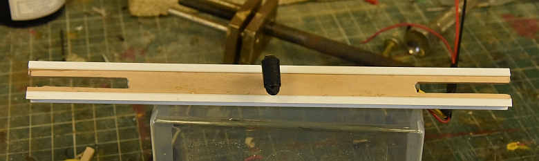
A single piece of limewood 10mm x 3mm 175mm long with a slot cut into each end as shown 4mm x 35mm. A single 2 aspect signal head was cut from its post with enough post left on it to be squeezed into a hole in the centre of the limewood strip. One side of that protruding post was cleaned off so that a wire could be push fit into the hole and serve as a feed for the lamps. This arrangement was then glued together to form the basic gantry structure as shown here:

The rotary switch will control both the lights and the points in conjunction with a CDU and 4 push button switches. Although its possible to control the points using one push button on the feed side of the CDU I have chosen not to do it that way.
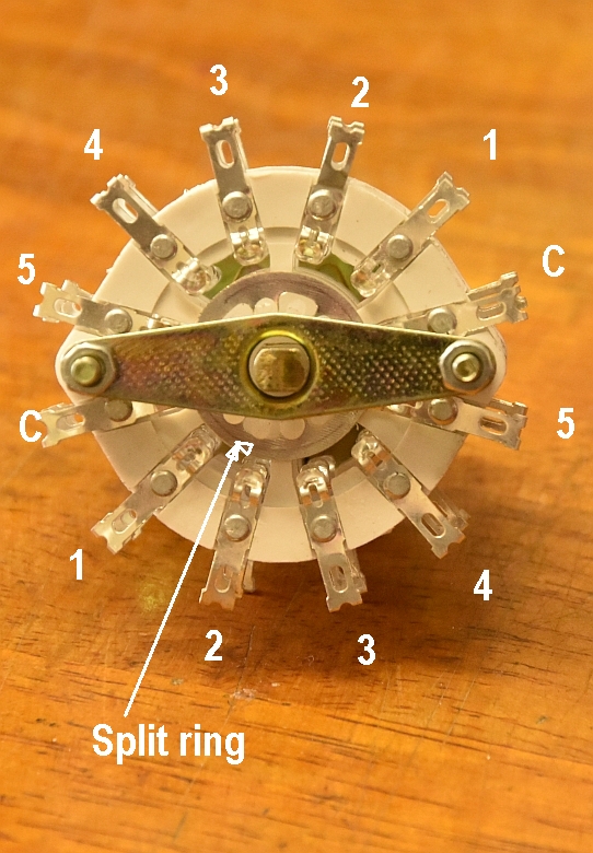
The switches arrived today and here is one:
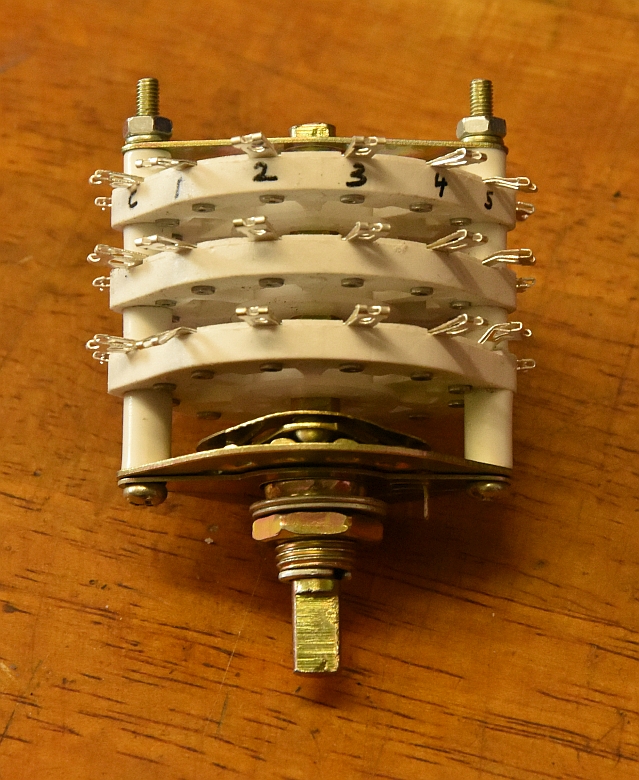
The way they work is through a split system. Each side has 6 contacts. The first on the left is the common feed contact, (lettered C on the picture).. The rest are individual contacts numbered 1 to 5 from left to right. This is the same on the other side of the switch for each wafer. Therefore it makes up to a 6 pole 5 section switch!
Here is the basic gantry in situ:
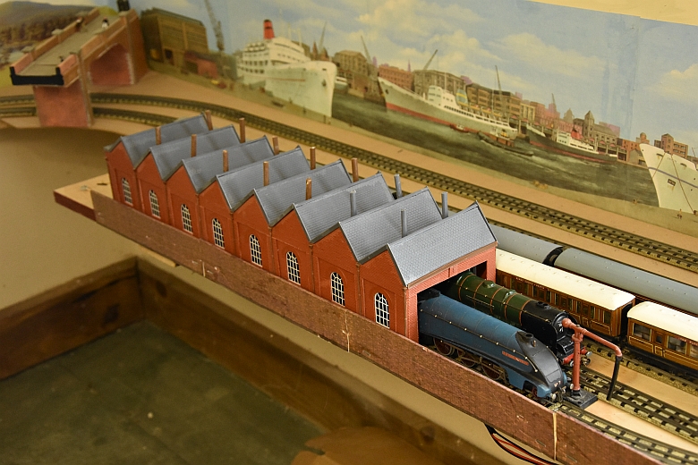
The engine shed will house 4 large locos separated by isolation sections and I will add a spur for shunting purposes off this section. Here are the 2 Wills kits I used to build the shed:
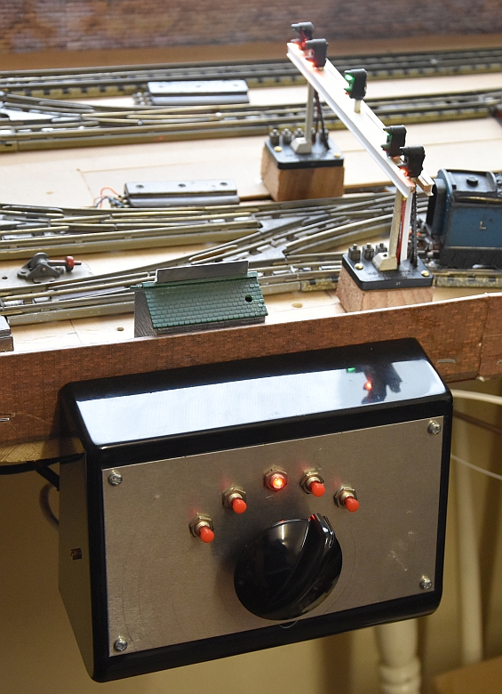
The method of working is to set the road using the control knob and then adjust the points by pushing the button the knob points to. What follows is a rough how to:-
Connecting the gantry up, here are the tabs on the under side of the lights identified.
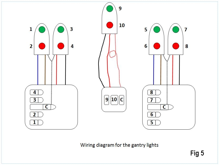
Next inside the control box, the connections for the points and diodes also the push button switches..
click any picture for a larger view.
Logic Principles
4 roads
3 points
4 push button switches
6 pole 5 way switch
3 diodes
one setting has all lights to RED