My O Gauge Journal on
Modelling the GWR
A personal Journey
Building the tippler
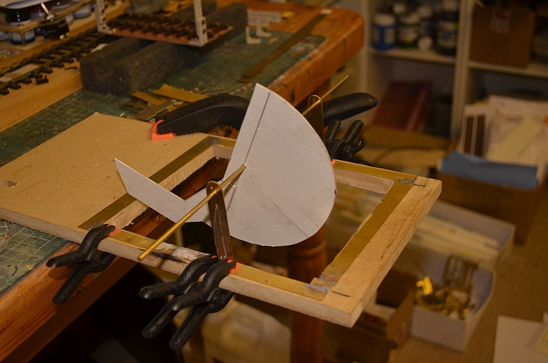
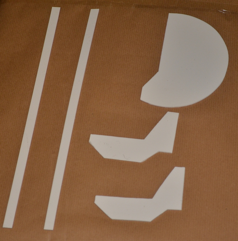
I started by cutting a hole in the baseboard 15cms x 17cms. Using card I created the shape for the main tippler as a semicircular shape and a support for the track. Finalising the clearance of it as it rotated was a precursor for sizing it acurately.
Calculating the diameter of the circular supports with an extension for the rail platform created a circle of radius 6.8cms. The shape created as shown below will be used to counter balance the wagon and track when it is in position.
Click any picture for a larger view
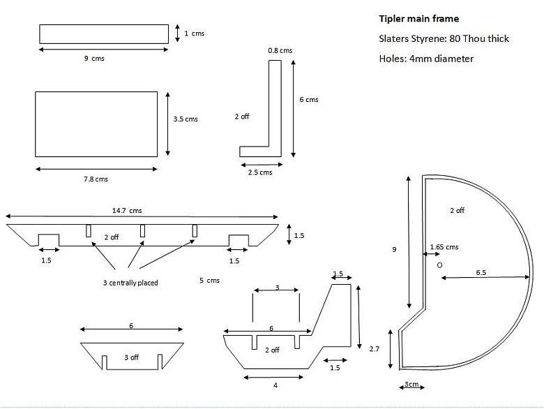
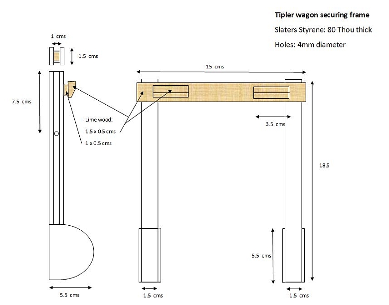
Here are the dimensions I used to create the structure. It is divided into three parts as shown below: (click image to enlarge)
The rail platform section is glued onto the circular section. That section is a semicircle plus 1 cm. It rotates freely into the space provided in the baseboard for the coal hopper to be built and fitted. I will use 4 of these to make up the main supports for the platform.
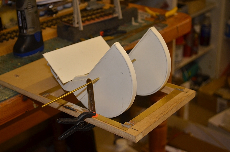
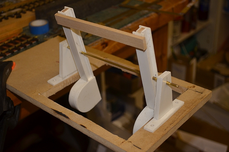
I created two side pieces in Slaters Plastikard Ref: 0180, 80 thou thick and two brackets to support the track platform. The strips are to add thickness using wooden supports as shown below.
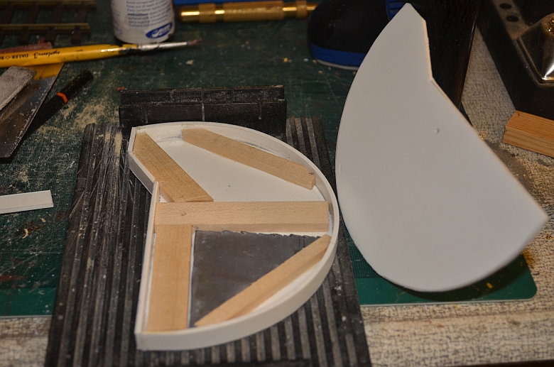
I used lime wood, (16mm x 5mm), to create support for the other side of the structure. The grey triangle is a piece of lead to help the shape balance once it is in situ. The next stage will be to fit the platform support and then work on another similar piece for the other end of the tippler. I have experimented with rivet detail and this works quite well on the plastic, but more on that later on.
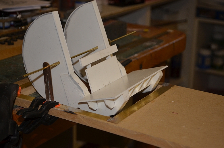
The platform supports are glued in place using Mek Pak or similar, making sure they are square to the long length of the counter balance weight. Here they are with a wooden block support waiting to have the edges filled in with styrene strip.
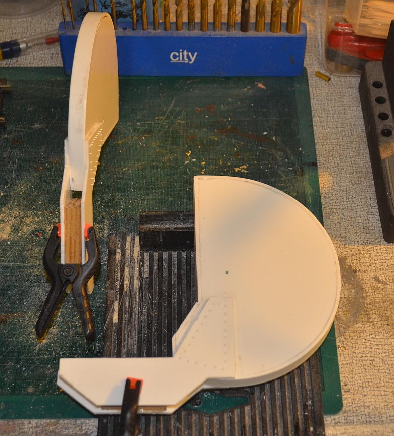
You can just make out the rivet detail I put on before gluing the platform supports on.
The platform connects the two platform supports together and brass tubing has been inserted into them to act as bushes to help it rotate.
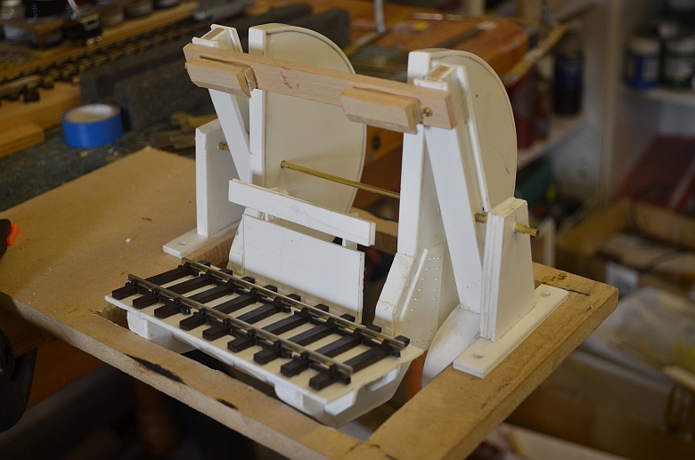
Here is the wagon backplate and steady in place attached to the platform. The steady, (the small top part of the steady), is two thicknesses deep to allow for clearance of the brake parts of the wagons not to foul the steady.
Here is a closer view of the underside of the platform.
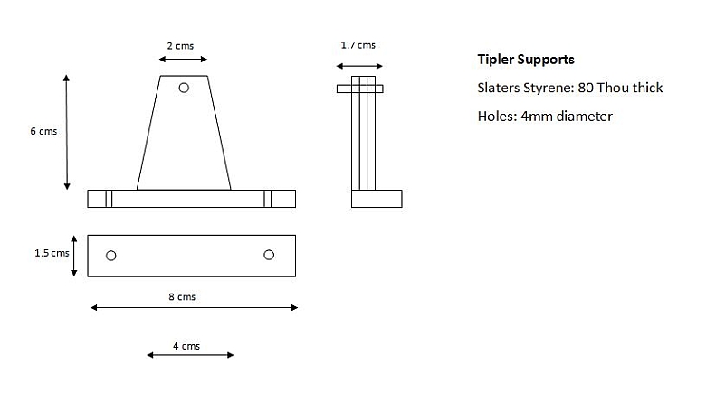
Currently, I'm using brass uprights to act as bearings for the rotational axle. I will replace those with suitable styrene supports with brass shells on them like the design below:
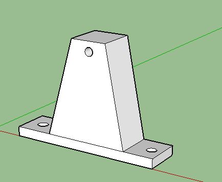
The base is 2 strips thick and the upright is 4 strips thick.
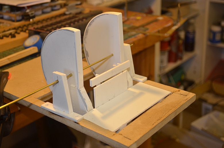
Here are the made up supports in situ:
The next job was to make up and fit the securing arm for the wagon. I chose to counter-balance this structure with lead weights in semicircular forms at the bottom as shown here|:
You can see from the cross section of the arms how I put them together using styrene sheet and lime wood.
I shaved the two wagon steady supports so that they made a good fit onto the top of the wagon.
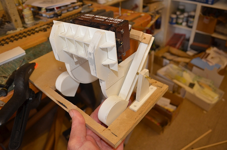
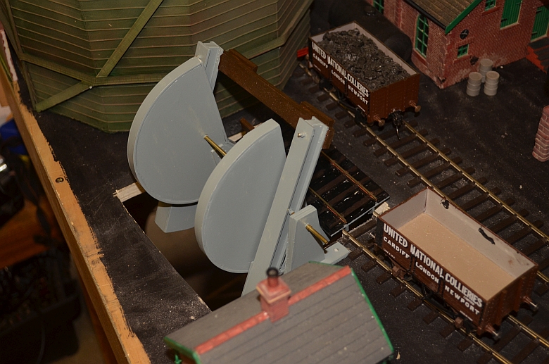
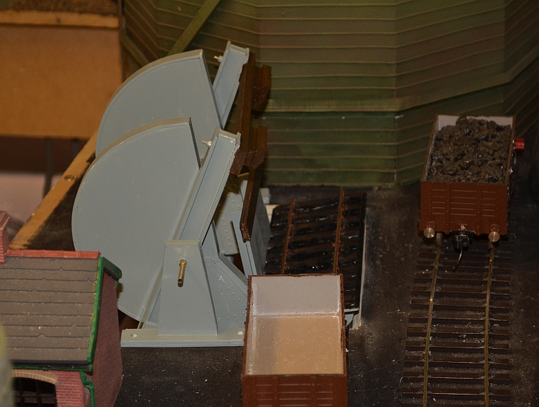
Here you can see how the supporting arm keeps the wagon on its tracks as it rotates. No springs or extra gripping is needed for this if the weighting is sufficient.
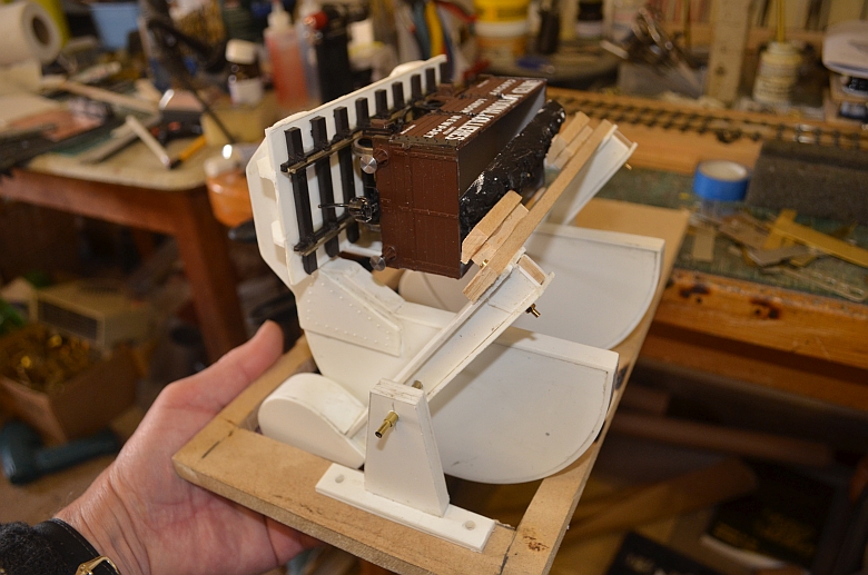
Here is the Tippler painted and in situ to check on clearances.
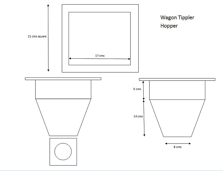
The below baseboard bit, the hopper to catch the off loaded coal.
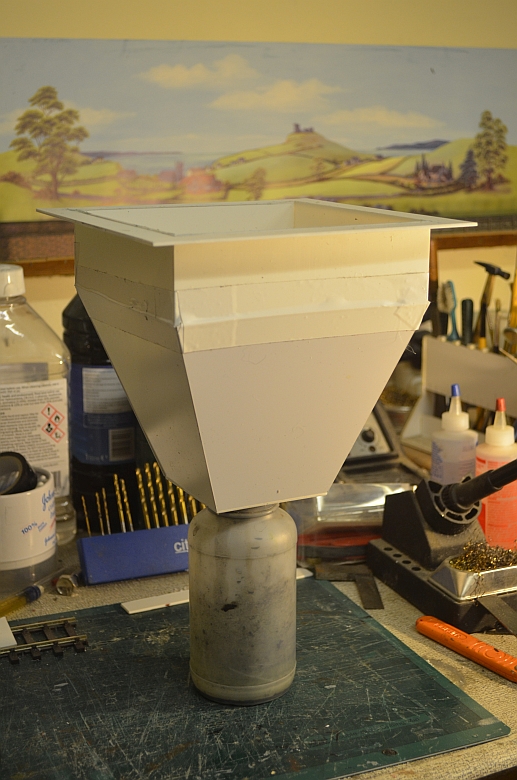
The hopper was made using styrene panel with a lip at the top so it can be fixed under the baseboard. The bottle is removable and used to replenish coal wagons. Here are the dimensions, click to enlarge.