My O Gauge Journal on
Modelling the GWR
A personal Journey
2. Building the locomotive body
Making up the running plate and adding the splasher plates and covers is straight forward and was made easier using both a soldering iron and micro flame gun. Most of the issues in soldering come from a lack of providing enough heat to a particular area especially where large pieces of metal are concerned. A micro flame gun helps an awful lot in those situations.
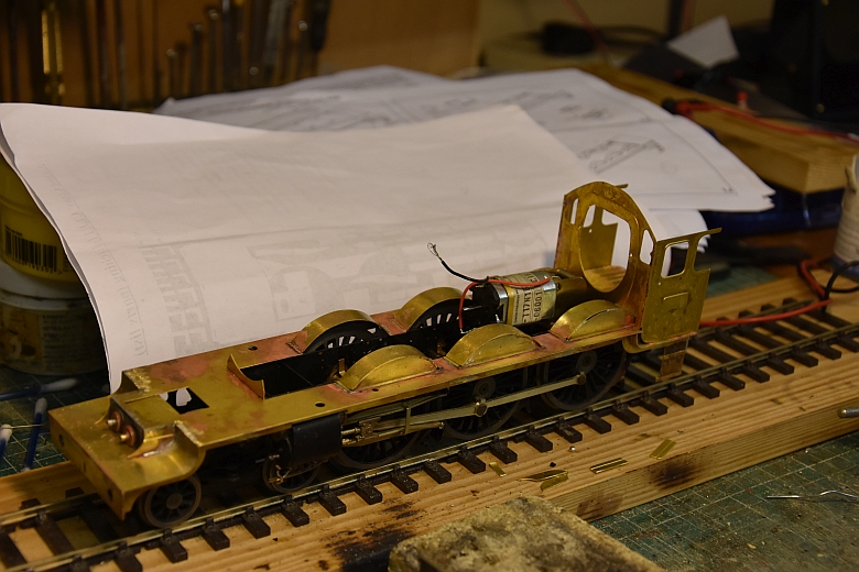
The cab sides and boiler back plate and at the front end the inside cylinder covers are now in place after a little fettling. As this body is of the early castle Windsor Castle, the inside cylinder covers were as selected. Not sure how well the cab fit is here but adding the firebox and boiler will soon alert me to any discrepancies
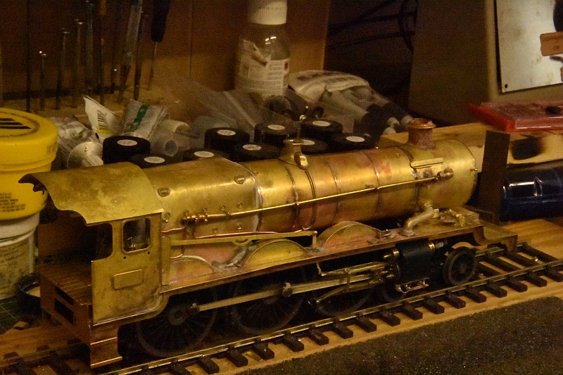
Smoke box and boiler have been rolled by hand and soldered together, click on the pictures below to enlarge them:-
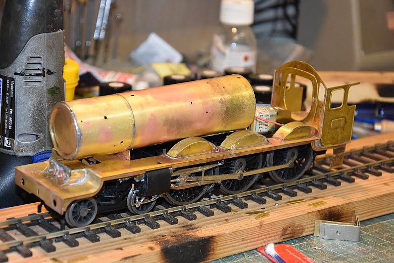
The firebox has been folded up and the front end filled over in readiness for shaping. The smoke box hinges that were missing are here and fitted as shown and the chimney etc is in place although not permanently.
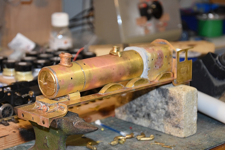
I didn't check properly which way round the smoke box should go but in spite of the drilled holes indicating I should have put it together the other way round, I had made the right decision after all as the steam pipe holes were in the correct position so filling in a small hole and drilling one on the other side sorted out logistics for pipe work.
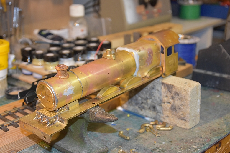
Cab roof has been bent to fit the sides and front but not secured as yet.
Cab and boiler have now been soldered into place. The steam pipes have been soldered but only at the non boiler end the other remaining free to move slightly.
Other small pipes have also been soldered into place. I use copper wire as it is easy to bend into place.
Gaps in the boiler connections have also been filled in.
The interior of the cab is now fitted using a JLTRT castle cab kit.
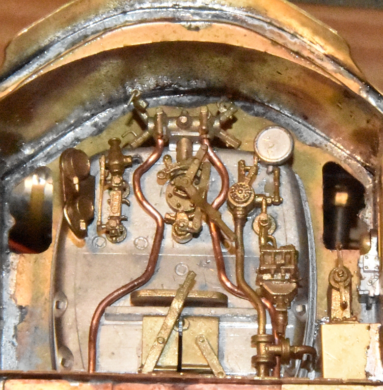
As always a couple of extras to finish the cab off include a Microcast components from Hobbyhorse ATC bell, a reversing lever and housing.
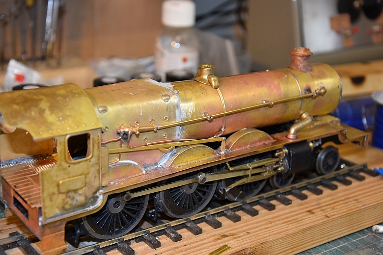
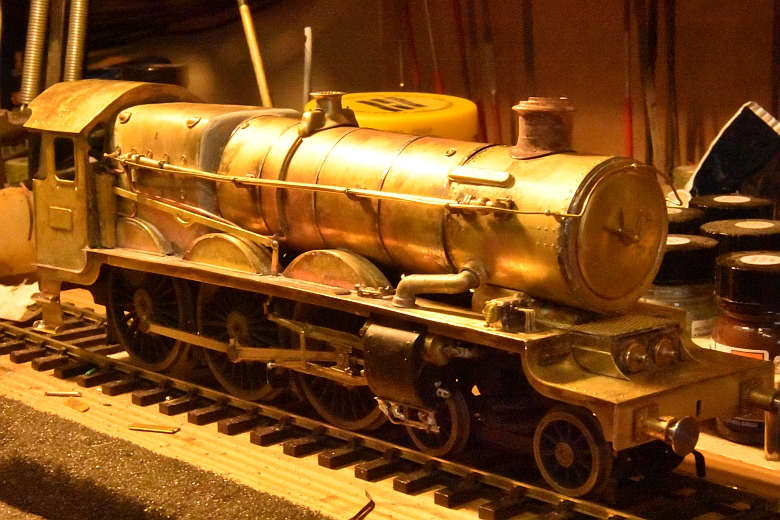
The boiler bands have also been fitted. I used Phosphor Bronze strips to create the boiler bands, (the sort you use for electrical pickups). They solder and bend really easily and look about right. I get mine from Squires S1220 about £3.50 for a pack of 10 x 6” strips.
A view from the front this time. buffers in place, and hand rails inserted. The footplate steps are also soldered up.
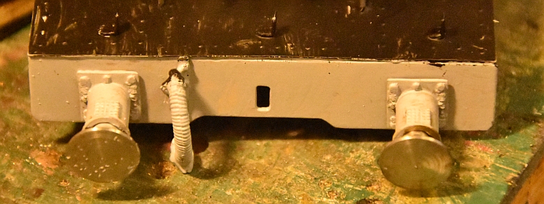
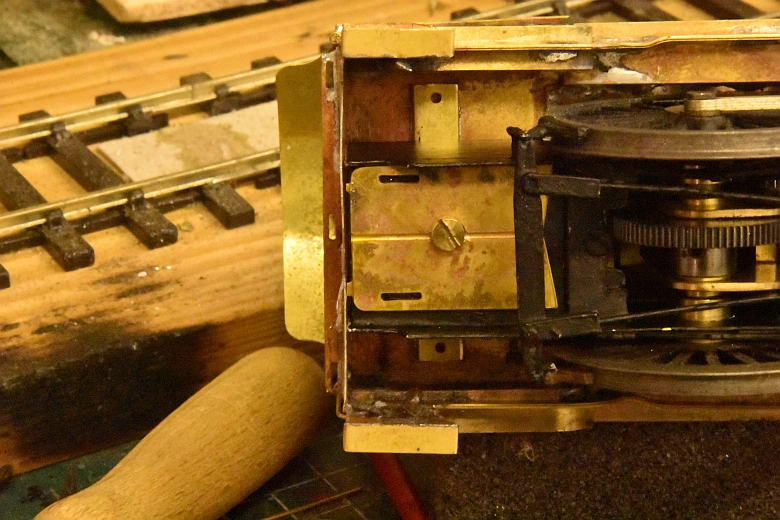
Fixing the body to the chassis is by a simple slot method as shown below by soldering a flap behind the buffer plate. The chassis then slides under it.
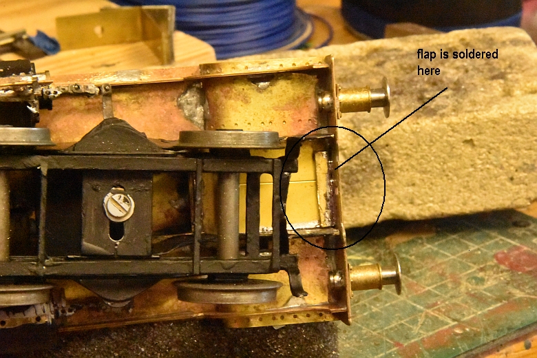
The cab end is secured with a single bolt secured by a nut soldered onto the chassis frame. The result is a secure arrangement easily dismantled if necessary.
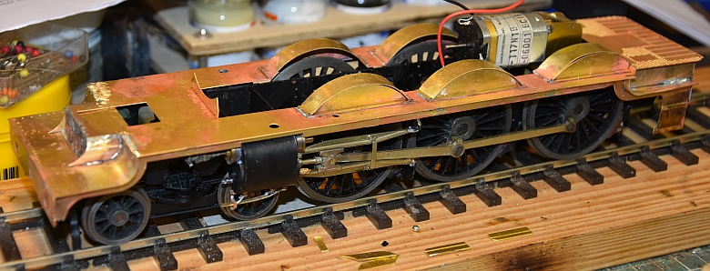
A preliminary testing on the railway to make sure that the wheels are on the right way round, (I'm using the American method of pickup using the left hand wheels on the loco and the right hand wheels on the tender. The two coupled together using an insulated coupling, (usually a plastic strip). Issues with short circuits caused by the front bogie catching the mainframe meant fettling some of it away as well as the inside of the cylinders. Checking and making sure all the isolating wheels were on the same side, (including the bogie wheels). Finally, trialling the loco on the track with the boiler in place as well to make sure that none of the driving wheels were touching it. Once all short circuit possibilities have been eliminated its time to move on to base painting the body and chassis parts.
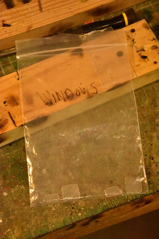
Finishing off with the windows and the lamp brackets. First the windows. Cut from plastic and shaped to fit snugly into the surrounds. Here they are ready to be fixed once painting is completed.
The three lamp irons are fitted onto the front of the chassis as shown here.