My O Gauge Journal on
Modelling the GWR
A personal Journey
5. Building the tender body
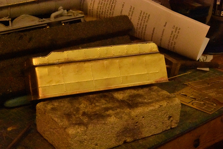
There is an extensive amount of riveting to do on the tender. Starting with the sides its necessary to obtain a good drawing of the tender to calculate the number and position of the rivets as there are no guides on the etches
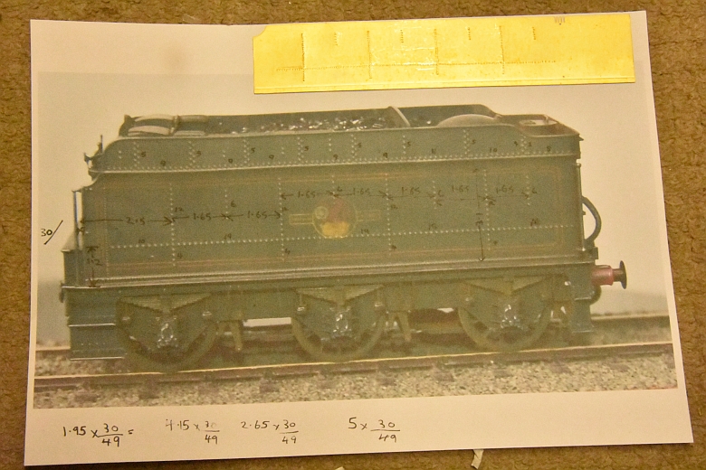
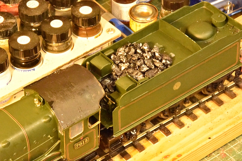
By scaling the picture against the etches its possible to get fairly accurate measurements. Mark these out on the etch and then proceed to rivet each side, (not an easy job for me). You can see one side almost completed at the top of the picture. Here is a close-up of the measurements I calculated. Not sure how far apart the rivets should be either! Click on it for a larger view.
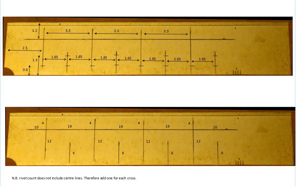
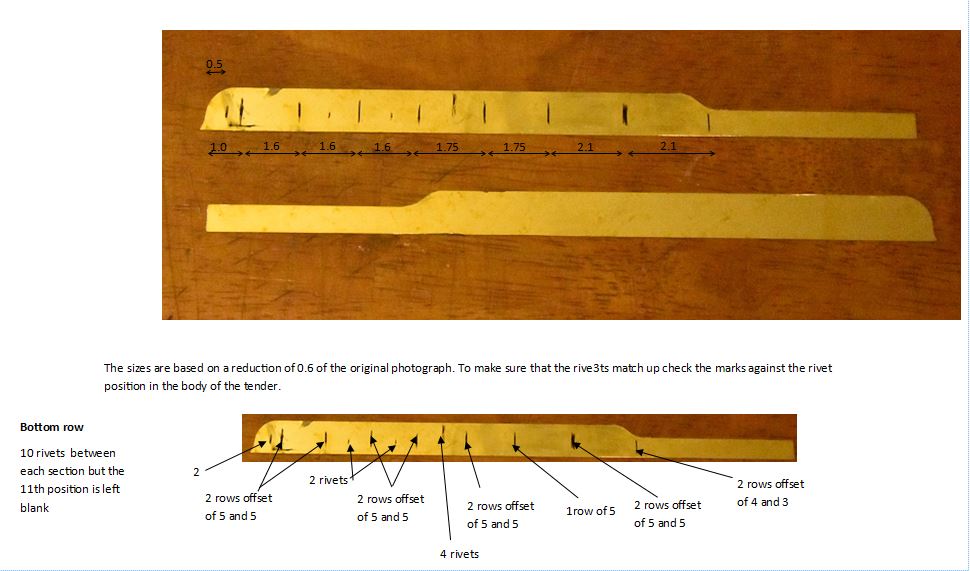
The dimensions for the riveting the top lip of the tender are as follows, (click the image for a larger view)
I found the riveting quite difficult as there is always the issue of getting a straight line of rivets into awkward or small sections., so here is my humble attempt at the almost finished stage.
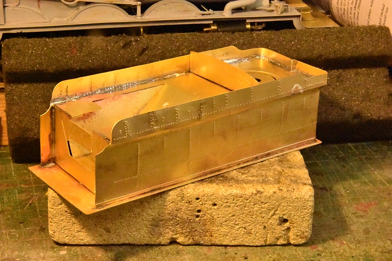
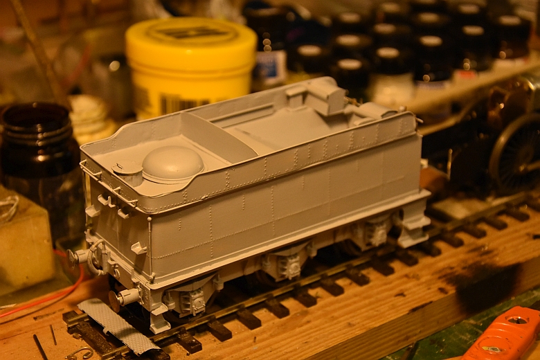
Soldering the piping to the top part of the tender turned it into an acceptable attempt as shown here, (click to enlarge):
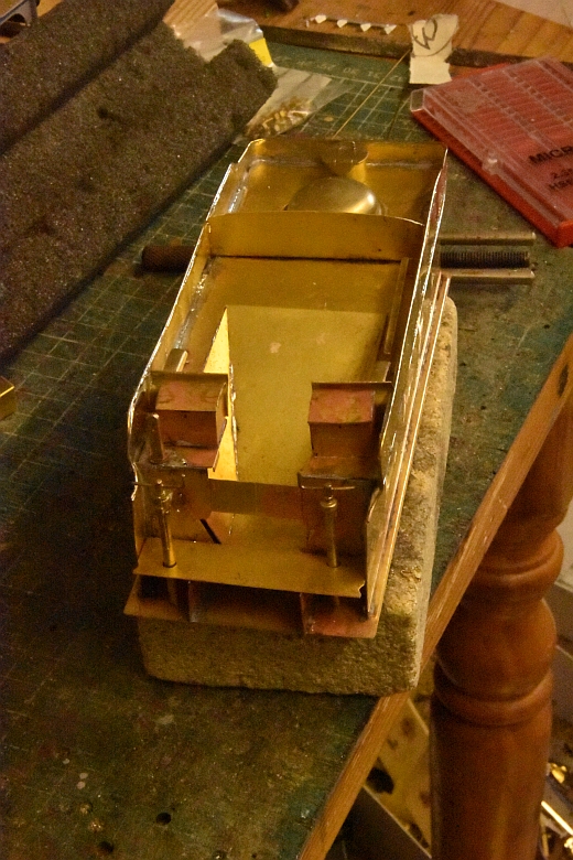
Adding in the toolbox guard plates, fire iron rack water tank vents. The tool boxes and the water valve handles. The filler lid and dome at the rear of the tender top. I used a mixture of solder and superglue to fix theses parts depending on space available.
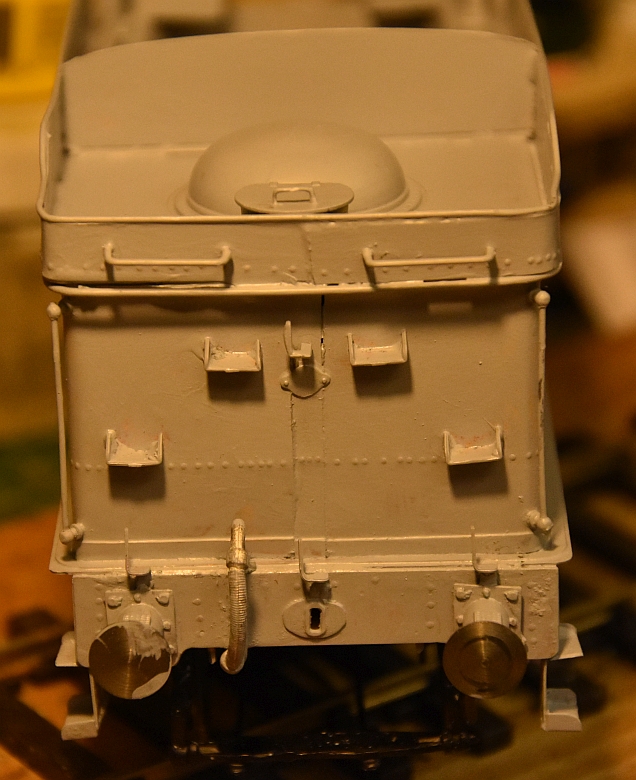
Finally, the back end of the the tender needs some foot steps, a plaque and a lamp holder along with a couple of hand rails. So here they are:-
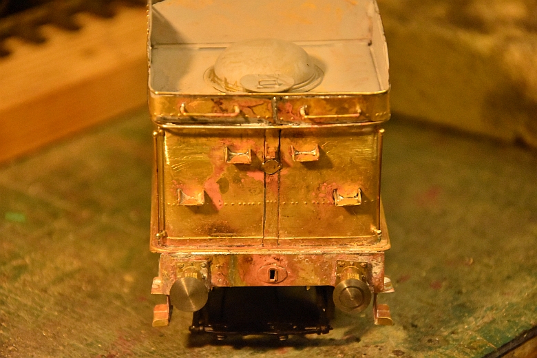
A JLTRT coupling will complete this end once I stick the brake pipe connection back on again!!!!!!!
Finally, putting the three lamp iron brackets above the buffers. Etch primer has now also been applied.
A couple of base coats of etch primer applied by brush.
Painting and lining it is covered elsewhere but all that remaons is to put coal in.