O Gauge Modelling on the GWR
A personal Journey
Developing a control panel for the railway
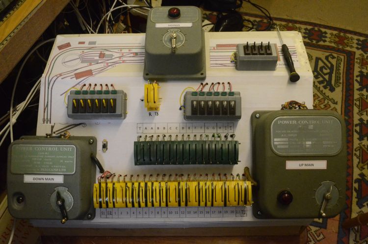
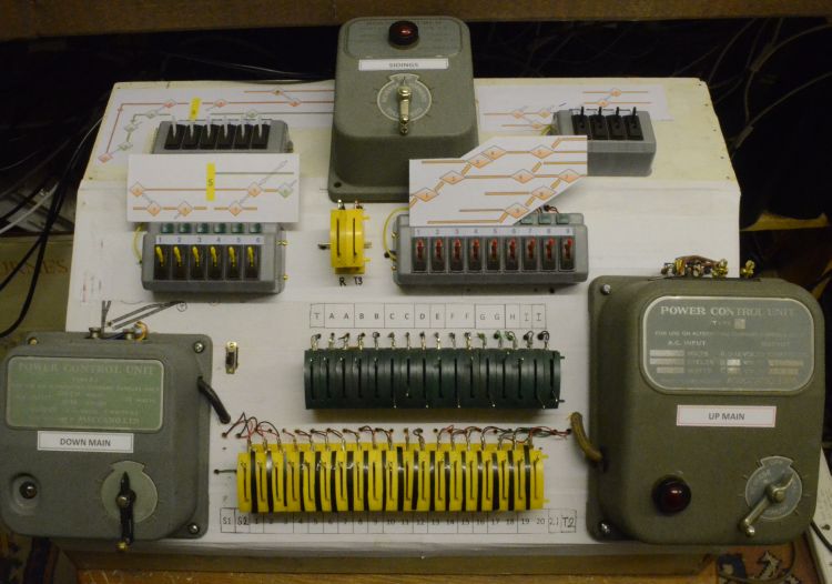
The control system of the layout consists of three controllers. One for the up main, (Type A3), one for the down main, (Type A2) and one for the sidings, (Type C3). The track has several isolated sections. On the main in the station area and several in the sidings. These are controlled by 16 Green Hornby switches some working in pairs to isolate a specific area of track others just isolating a piece in a siding. The colour light signals use 24 Yellow Hornby switches of which 5 are pairs. This is what it looks like:-
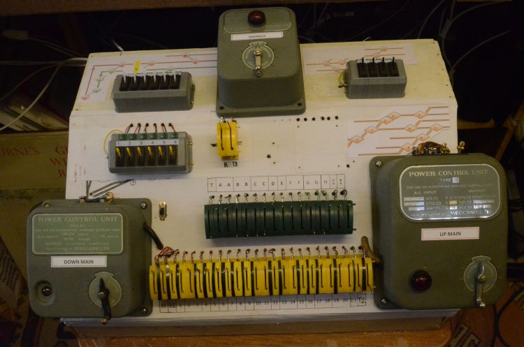
But in an effort to update the control panel I have had to move some switches namely those from the bottom right to the top left hand corner as shown here:-
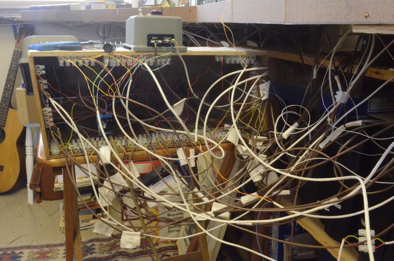
The other side of the control panel is not so tidy as shown here;-
With new 'mapping' diagrams and the switches numbered. I have chosen to move over to Peco switches as they seem to be superior in operation to the Hornby ones and indeed I had previously tried Eckon "Lectralok" lever switches Nos EE4. These are the passing contact switches and half the price of Hornby switches and so I thought better made. here are a bank of six in place ready to switch points. But herein lies a tale. Please read on and all will become clear.
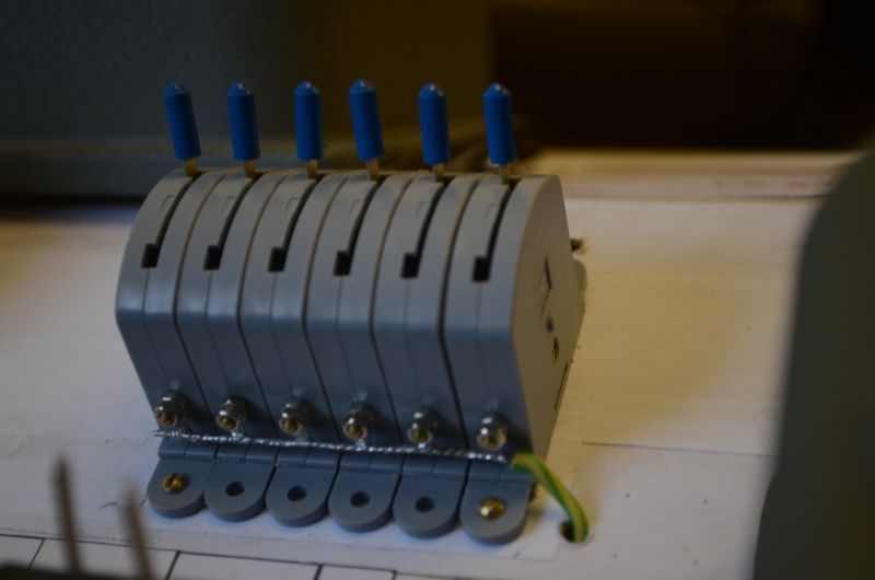
The handles are covered in a coloured sheath, (in this instance blue), and I have connected the common feed with an arrangement of wire soldered to 6 tags that are included with the switches, (1 cm apart). The plastic fixing brackets can be used either as shown or in the sides of the switches. There is a groove where the tags fix and I found that by opening up the grooves with a small file I could slide the tags in and secure them with Plasweld. I could have only put the four tags in that are screwed down but chose to add tags to all the switches.
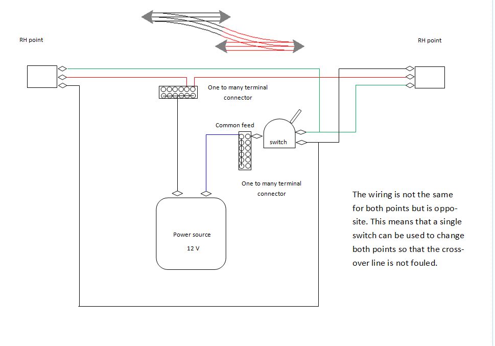
Here is a wiring diagram i used to connect the switches up to my points. Click on it for a larger view.
BUT, and this is a large but. I discovered that out of the six switches two of them appeared faulty. One in particular appeared stiff and then would not break the circuit in one direction. i took the switch off the bank and opened it up. This is what I found. You can clearly see that one passing contact switch is completely bent over so that the lever will still make a circuit if in that position. The whole setup is very flimsy and relies on the contacts being set just in the right position so that this doesn't happen.
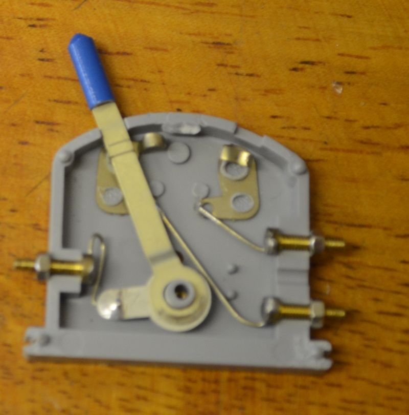
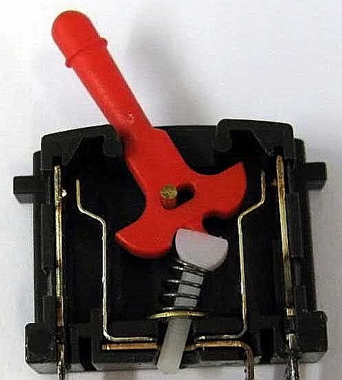
Its a very crude setup and prone to fouling. The lever is also made of very thin strip and bends easily. If this happens its likely that it will lever the contact up again and the same issue will rear its head. My advice is to invest in what I consider the best switches, (those made by PECO), as used on my O gauge layout as those are much better in construction and reliability. Click here to see that installation. Here is an inside view of what the PECO switch looks like, (see below). You can see how much more robust it is to its competitors and somewhat foolproof. I feel I have wasted £27 on inferior kit that is likely to damage the points they are controlling.
Now all the points have been electrified and I've doubled up the 5 double signals, (this has reduced the yellow switches by 5!!). I have also put in place 4 diagrams to identify switches.
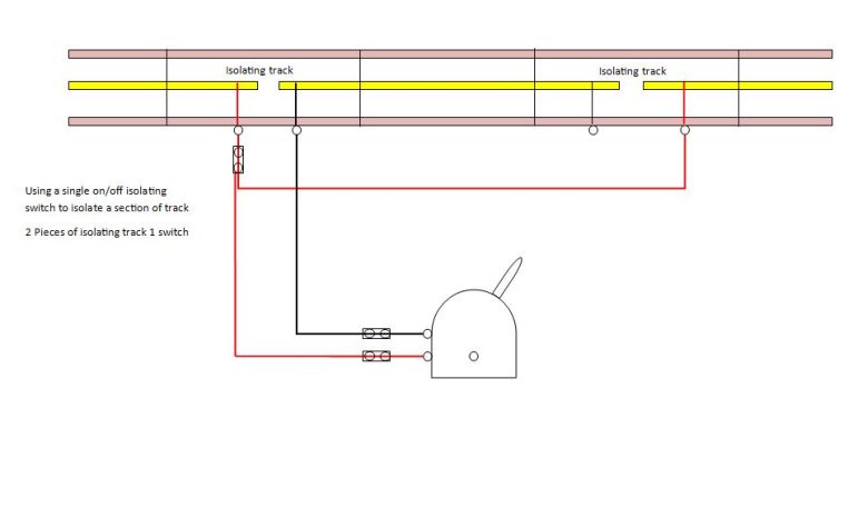
Unfortunately, just like any project, after the preliminary setup the additions made will often over complicate the original plan. This is the case now with many many wires attached to switches that then feed all over the layout. In an effort to address this i have decided to redesign the control of the layout. Two aspects are important here. First, in a similar way to how my O gauge layout is controlled I am going to install point, signal and isolation switching in four places along the edge of the layout each on its own box. Secondly I have been able to see that isolation sections do not need two switches to isolate them. With a simple wiring diagram as shown below, I can use just one switch. This can be te same for signals at points where one switch can operate both as described elsewhere. The controllers will remain in a central position though.
Panel Construction
Using three original Hornby Controllers
and banks of switches to control isolated sections, points and signals