O Gauge Modelling on the GWR
A personal Journey
Redesigning the electrical control working of the railway
The electrics came to a head when I started to include the point motors to control both points and signals. I was running out of physical space on the control board and it was creating problems rather than solving them. So I broughtproceedings to a stop and considered the situation with a view to redesigning how it would be run. I hope what follows will be of use to others who find themselves in a similar position.
One of the issues in developing a control system for your railway is that as the railway develops, the system that controls it often becomes added to as a 'bolt on' procedure. This can lead to all kinds of problems. Not least a multi-complex wiring system, too many switch controls, some in the wrong place and arranged in the wrong order on the control base. Keeping everything in one place as i found on my o gauge layout is not helpful and you still find yourself moving backwards and forwards during running whether points are manual or electrically operated.
Therefore I have decided to take a leaf out of my O gauge layout development plan and redistribute switching to 'sections' as opposed to keeping everything in one place.
To do this I will need 4 control sections placed at the edge of the railway roughly within the area that they will be controlling. For this i have ordered 4 Camdenboss Vario cases that can be fixed under the baseboard to give a protruding slanted face on which to fix switches. As they are enclosed boxes the electrics, (CDUs, terminals, etc) can be hidden inside. the size I have chosen is:
143mm x 170mm x 55mm and priced at £5.04 each + VAT from Rapid Electronics.
The main control panel will house the three controllers and feed the four boxes and this will significantly cut down the amount of wiring that currently looks like a spaghetti tree gone wild to something more manageable. it will also mean that electrical faults will be much easier to trace.
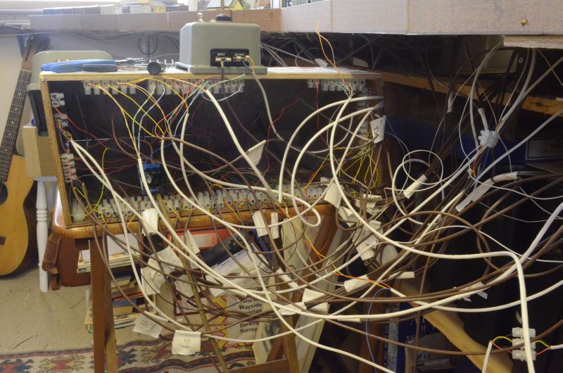
There's also a loose board in there with 4 CDUs! So much to go wrong even though most of it is labelled!!!!!!
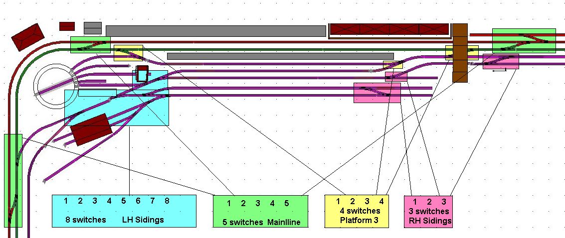
Here is a plan of the distribution of control across the four areas of the layout. Click on it for a larger view.
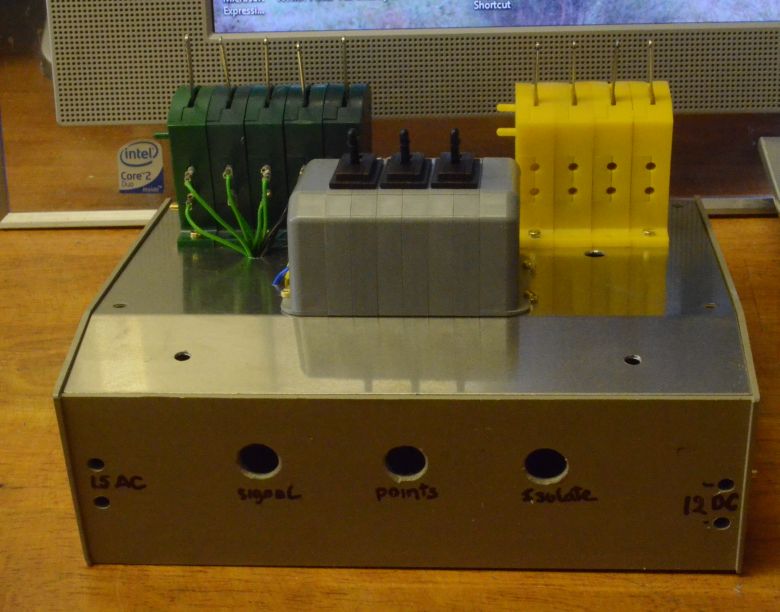
Starting with the smallest one that will control the right hand sidings I set about planning the control box. Here are the results 2/3rds completed.
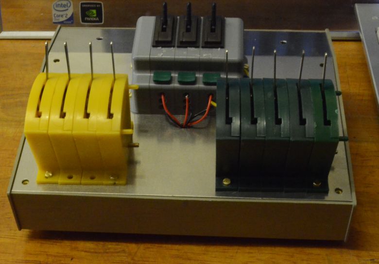
3 banks of switches to be wired internally as shown here.
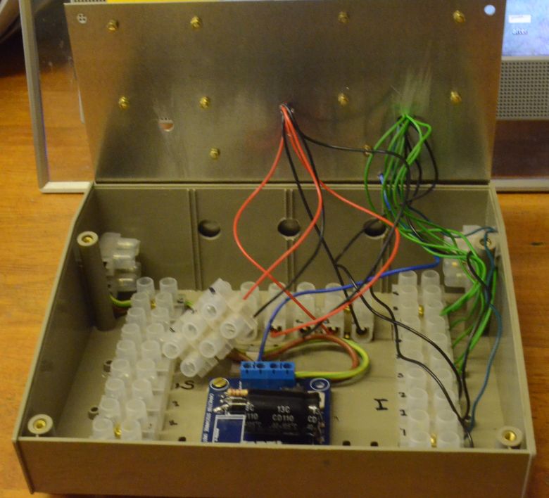
The input/output holes at the back and the two power feeds on the right and left hand sides as shown here.
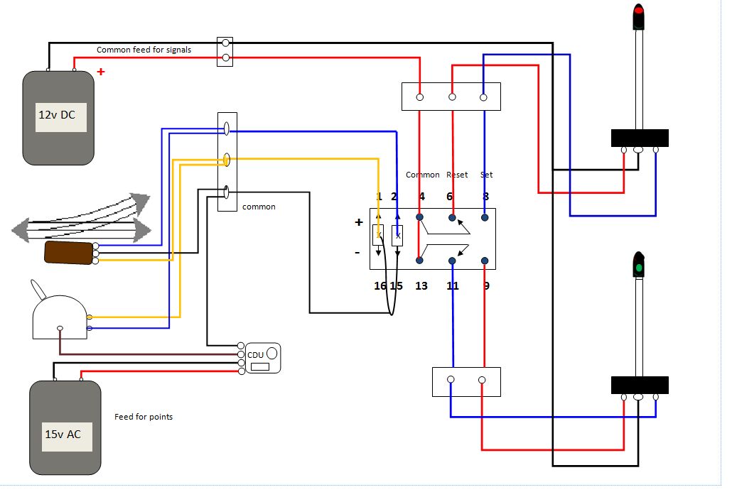
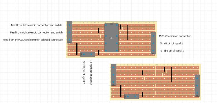
A further development is to remove the need for separate signal switches. I am sure that the point lever can control both using relays. Here is a wiring diagram that I have put together with help from Brian Lambert, (http://www.brian-lambert.co.uk/). But more on that soon.
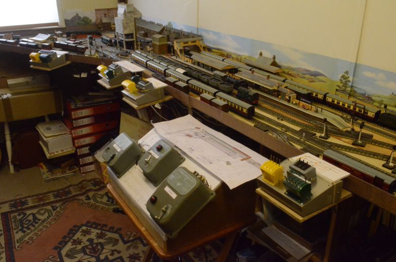
The four sections control panels have now been put together and wired up. All signals and points work. I set the signal levers to be default RED. Which means you have to pull them off to set them to GREEN and give right away. The points default to straight ahead. If i can get the wiring of the above organised onto a stripboard all the yellow switches can go. Here is the layout with the new control panels. Another development was in the current supply for the signals. As i was using the Hornby controller B supply it was designed for a low number of signals or accessories. I was exceeding that and causing the contact breaker to activate on circuits A and C as well. (Most confusing). But the acquisition of a separate 12v controller that was rated at 3 Amps cured the problem. Something to bear in mind if you are creating a large layout!
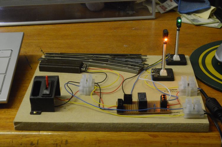
Here are my efforts in producing a circuit board from the diagram above. The point is using the straight road so the green light shows that whilst the red light indicates non divergance.
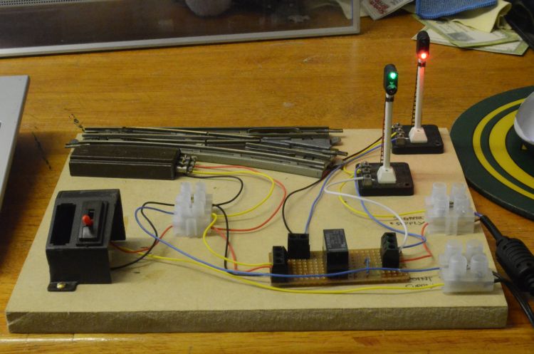
Here the point has been changed to use the divergent road and the lights now reflect that change. The latched relay controls this and is activated by the solenoid of the points. They are in two unconnected circuits and the one controls the other.
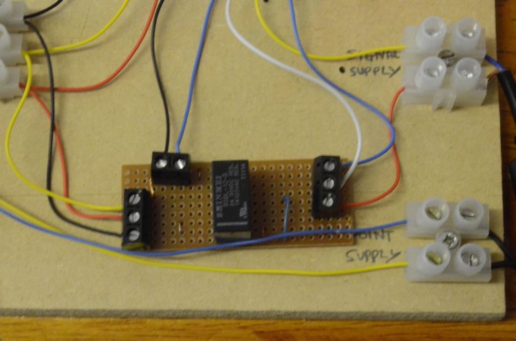
A closeup of the stripboard circuit. As I'm only using this as a test piece with one point I have omitted the CDU.
And here is the detail on what was done to the stripboard to allocate the components onto to it. I'm no electronics expert but this seems to work well. This is the board as seen from beneath. The components come through from the none copper strip side, (told you I'm a beginner in this field). I also used a 16 pin DIL socket so that I can replace the relay should it malfunction or wear out at a later date. There is nothing else on the board to wer out!
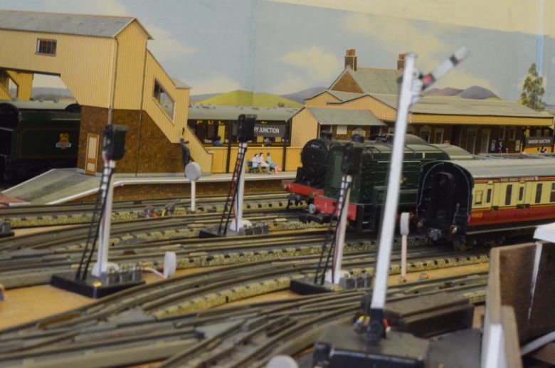
Why didn't I use semaphore signals?
The Hornby Dublo ones have big bases. This seems to make then stand up almost 3cms taller than light signals and just doesn't look right. Also the base is nearly 4 cms square and needs room to be fixed to the baseboard. Too near the track and this interferes with locos and rolling stock. If i were to use semaphore signals of this make I would want to put the base beneath the baseboard - but I'm not going there. I have one on my layout and it doesn't look right. Its wired up and works correctly though!