O Gauge Modelling on the GWR
A personal Journey
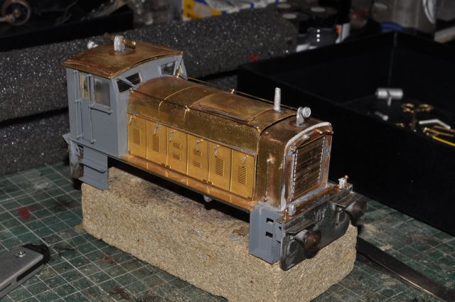
Building the Ruston DE PWM651
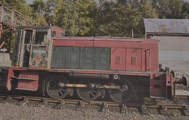
This is how it looks, (above), in somewhat sad but complete form. I chose to build Mercian's version and as it was on special offer at the Reading show I couldn't resist it. Added to that it was a Western Region loco and will work in my tar and coke works on the industrial area of my layout.
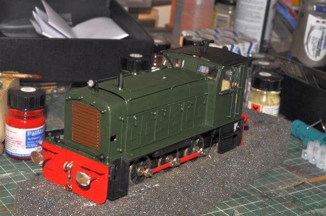
This is the finished article working in my Tar and coke works.
But what follows is how I built it and finished it off ready for work.
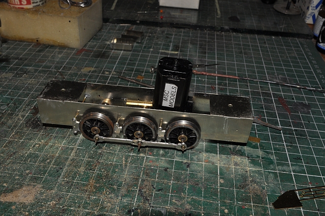
Made a start on the chassis. Laminated connecting rods can be a problem as they are prone to be slightly oversize when laminated together, ( also if the lamination is not totally secure they can display weak spots at the joins and have a tendency to bend. this can cause issues when trying to get them to run smoothly when the chassis is motorised. I spent some time adjusting the linkage holes and then gave it a long running in, (about 30 mins), in each direction before I was satisfied.
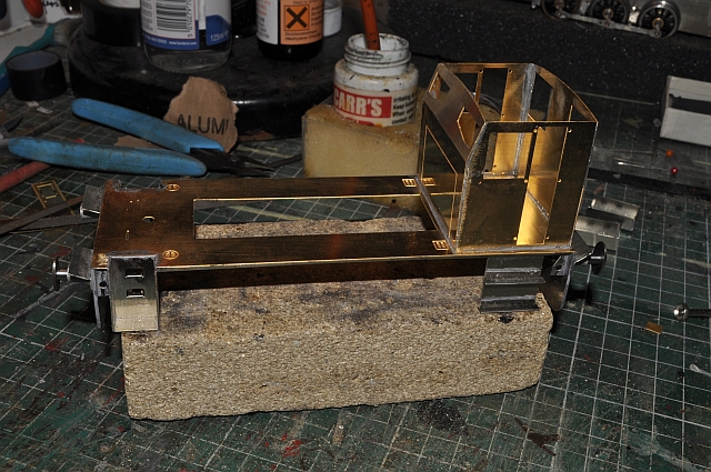
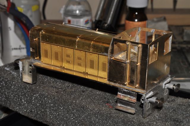
I then made a start on the body. This is a combination of nickel silver and brass parts and white metal pieces. The buffers come ready sprung but rotate and there seems no way to stop this. I have a plan which I will reveal later on but it entails careful soldering and use of pieces of brass
The solution to the buffer issue is as above. soldering a length of contact strip to the shank and the body. this gives a little flexibility whilst holding the buffers in the right position.
I found no mention of the lubricator in the instructions and no parts to build it. This diesel has one on the right hand side of the chassis. I made up a link as shown and this works well. the cam was a ready made 00 one from a previous life. Here are the bits i needed to make it.
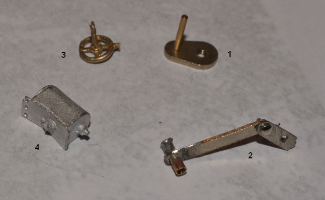
1 is the 00 gauge cam. 2 is the linkage i made up from brass pipe and strip. 3 is a valve wheel that comes with the kit and 4. is a bracket that resembles a lubricator which i used. I drilled a hole in the lubricator and made sure the valve wheel was a press fit as its attached to the body at that end. Fitting the cam was done by threading it onto the wheel thread and soldering it to the brass collet underneath.
I've been in constant touch with Mercian as there is a bit to be done to make this kit useable, in its present form its more of a scratch builders kit, but I'm pleased that we will get there in the end Mercian have been very helpful and understanding.
My friend Arthur Phucsake has just mentioned that the window frames should have been fitted before building the cab. But and this is a big but, the frames are so flimsy that it might not be possible to get a suitable result using them. Therefore I'm looking for alternatives and as such LTM might come to the rescue with plastic half round strip 2mm wide. The frames hold the glass in place and would have been a screw fit and possibly made from aluminium strip. I have suggested that this could form part of the etch itself and would involve two windows at the front of the cab and two windows at the rear.
More on that later but this is where its at now:
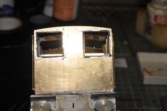
Regarding the window framing. i have decided to use 20 thou brass rod flattened with a hammer and then soldered round the edge of the window openings. This is the result:
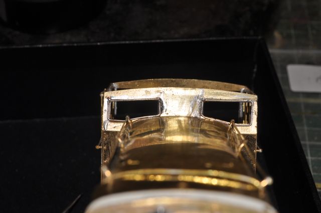
The side windows don't appear to have this so the back windows are now thus:
They are not badly fitted. What you can see is the top of the consul inside the cab!
I used the original frames as templates and then soldered them to the cab.
The side windows do not appear to have frames.
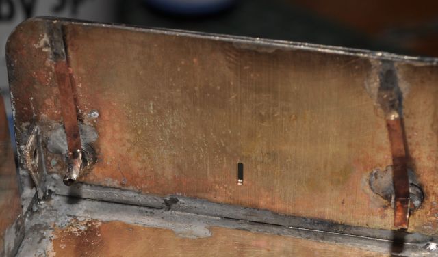
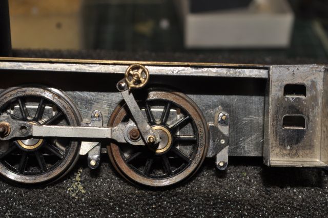
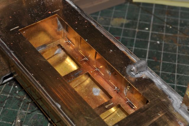
Back to the chassis. I had planned to use plunger pickups because of the nature of the chassis to body fitment. I got as far as fitting them and testing the chassis out on the DCC layout. but after a short run-in period the plungers began to short out on the chassis. There was a further complication in that the end of the springs occasionally touched the chassis. So i reluctantly reverted to the traditional type of pickup. here is what i did.
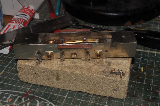
I soldered two lengths of laminate over the central area of the chassis flush with its top most edge. There is a cut along the bottom side to separate the collector plate from the chassis. Pickup strip will be soldered to this and will rub on the front and rear wheel rims. When the chassis is attached to the body it is concealed by the skirt on the body. You can see the plungers I used toward the bottom right of the picture.
Also had to reset one of the brake shoes as its placement was too near to the central wheel.
But before i do anything else it will now be painted.
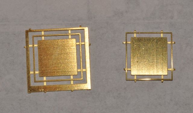
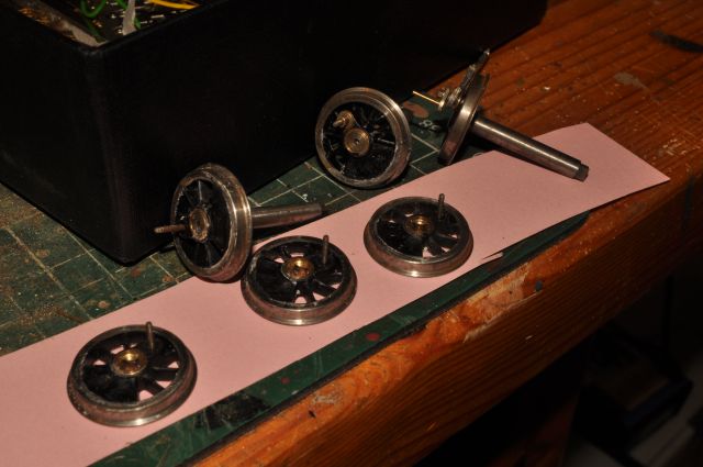
The wheels counter weights are also not provided for so i set about filling in three gaps with filler as shown here;
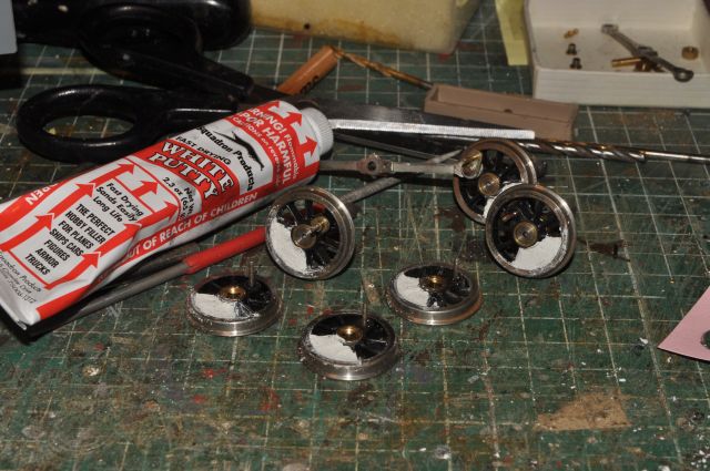
Although it looks a bit messy at the moment once dry it will be sanded to the right shape and painted black and will look like a counterbalance weight integral with the wheel spokes.
Here they are cleaned and painted:
The chassis is back together and being run in. There have been issues with the body in that handles for the inspection covers. 12 are needed but only 10 are on the sprue. Also brass rodding soldered from the inside is needed to support the handles at an appropriate distance from the covers. here is the way forward i chose:
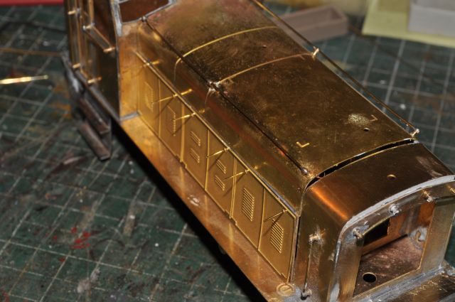
You can see from these two pictures how the rod was used to make up the spindles for the handles. This way it leaves the outside detailing clean. (click the images for a larger view)
And here are the handles fitted:
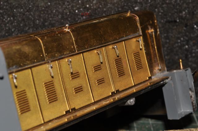
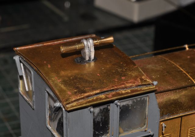
Now turning my attention to the roof of the cab. it needs annealing first as the edges must be bent back on themselves to make a ledge down each side. Also the rain strips need sweating onto the top of the cab as this will make for a neat fit of the roof. Finally the horns can be made up and soldered in place. Here is the picture of that completed process but the roof is left loose for now until painting etc has been completed.:
The front and rear lights were tackled next. \the best way to proceed with these was to solder the lights to a length of brass rod and use that to solder it to the body on the top of the buffer beam at the front and on the rear cab wall at the back. the two spot lights were fitted on the front as shown but on the back using an angle iron made up of some etch.
The window 'glass' unfortunately had a bad reaction to thinners and had to be replaced. This i did after all painting was finished and used UHU glue instead of Bostik. Here is the body painted:
As the chassis is a close fit to the body i had to solder the coupling hooks in place and grind the inside down to allow the chassis to be removed and positioned without the need to take out the coupling hooks each time. I don't see solid fitted coupling hooks a problem as all my wagons are sprung.
Finally a video of the finished article:
And fitted with Loksound DCC and sound card click here to view
Ruston Diesel
PWM650 was the prototype and used successfully in the WR in 1953. It was succeeded by the 651 class that had lamp brackets, mechanical lubricator, two tone horn, windscreen wipers and vacuum brakes.