My O Gauge Journal on
Modelling the GWR
A personal Journey
Signalling the railway
Signal building
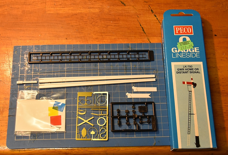
using the PECO LK-790 Home or distant signal kit
First the signal itself. I wanted something
that was relatively easy to build and flexible enough to make into
several versions on my railway. So I finally chose the PECO LK-790
kit. In this kit is all you need to make up a variety of Home or
distant signal variations. 90% of it is plastic with the smaller
items in brass. Cost in the region of £17.00
Materials
An LED in the lamp, (the mast has a hollow centre that could
take a couple of thin cables). The use of a Hornby point motor to
work the signal fixed to a vertical board attached to the bottom of
the signal as a single unit.
First thing to note, the
point motor needs some alterations. The 90 degree lever had to be
replaced with a straight piece of plastic supported by 2 washers
underneath and one on top. £7 for the point motor.
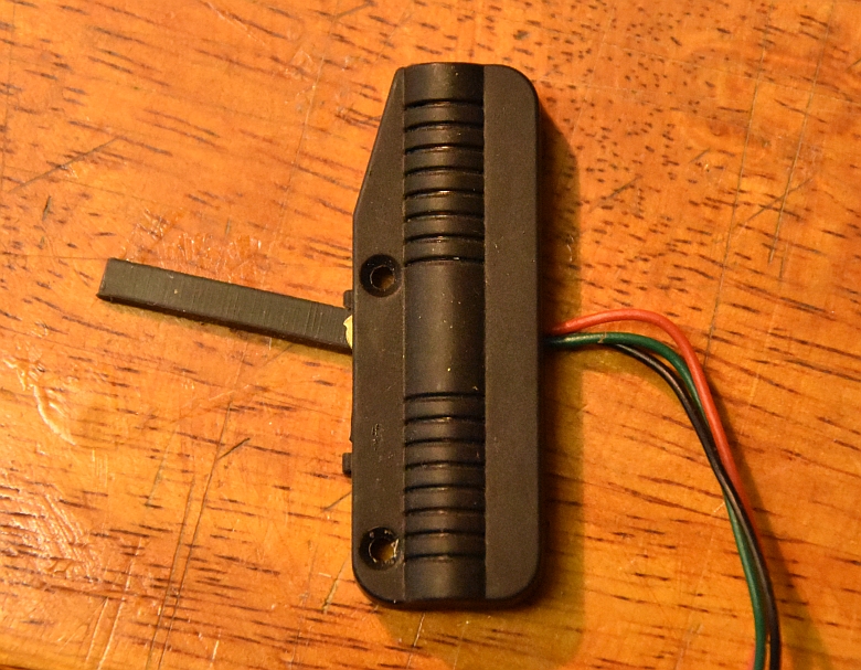 New straight lever to give vertical movement |
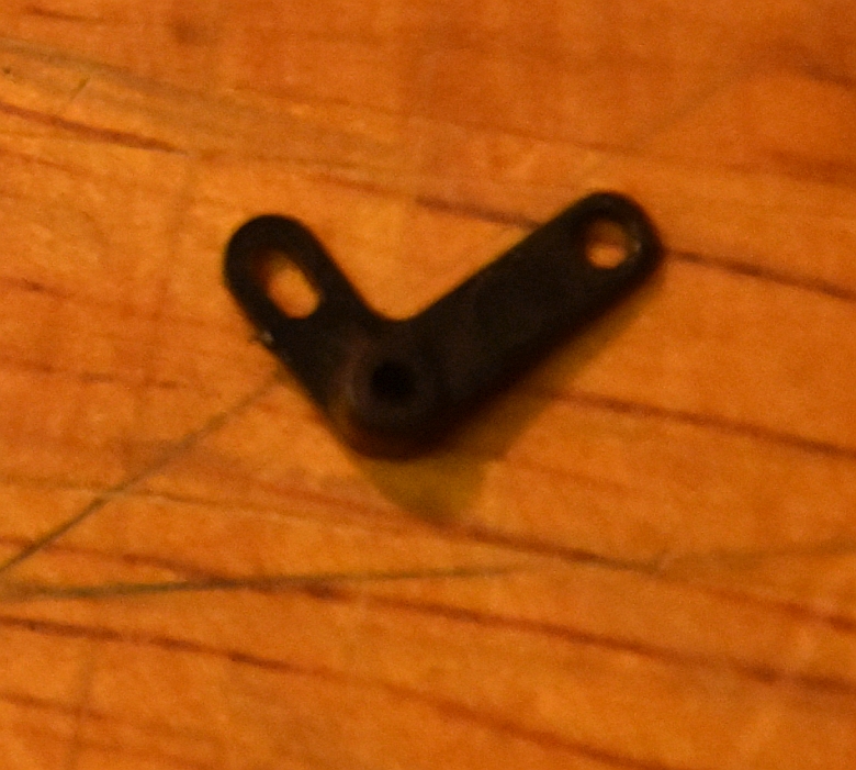 90 degree lever inside the point motor that had to be removed. |
To illuminate the lamp a set of micro LEDs can be used as shown here. Available from Express Models as a pack of four. These are very small but bright.
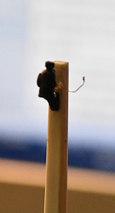
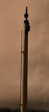
The micro LED wires are fed through a hole just above the 8mm mark on the side of the post. I used the other side to the one shown in the instructions so that I could feed the wires through and down the channelling of the post. The wires are not long enough to protrude out of the bottom of the post so thicker wire was soldered onto them to increase the length needed. A very small hole was drilled through the lamp so that the micro LED could be pushed through. I left about 15mm out to allow for this. The LED is a red one which when used with the spectacle plate of red and blue glass will hopefully show the correct colours! £5.95 for four.
Instead of using the
supplied ‘flat’ control rod guides I substituted them for brass
handrail knobs as shown here.
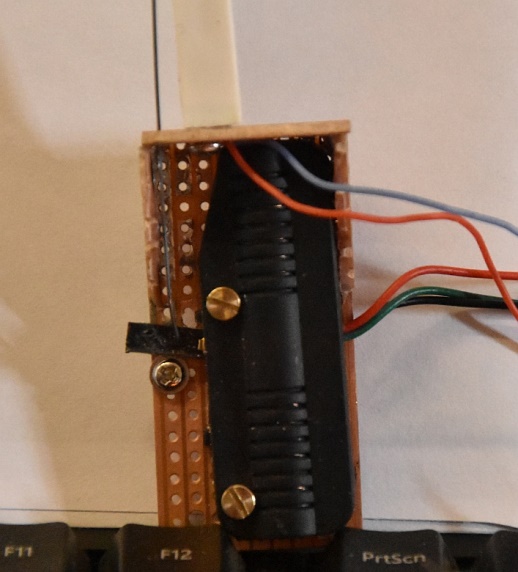
I made up a piece of
veroboard to act as a holding bracket for the solenoid. Attaching
the point motor and frame with a single self-tapping screw is ok.
BUT, the point motor doesn’t like to operate in the vertical
position. Its new arm returns to the up position as the bar in the
solenoid falls down due to gravity.
Post
script:
Having put this arrangement to the test there are a lot of
issues using this point motor. First it’s not designed to work
vertically, (like most other solenoids it is affected by gravity).
Secondly, it’s a really clumsy way to move something, (similar to
kicking a ball instead of rolling it carefully). Thirdly, it tends
to heat up if used several times in succession, (perhaps this is why
the Hornby point motor has ventilation slits in its upper body).
I have therefore abandoned this method and turned to using a digital micro servo and related control board instead from Heathcote Electronics.
I have
therefore purchased the following items from them:
Their bouncing semaphore
controller board, (£12.80), a digital servo and a servo bracket
(£5.00). The board requires a 12DV supply and a switch to control
the signal.
Important note: Using a
digital as opposed to an analogue servo has distinct advantages. It
is more accurate as it moves in much smaller steps, and it does not
‘fidget’ as the analogue ones tend to through electrical
interference.
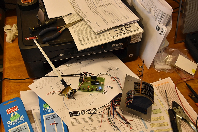
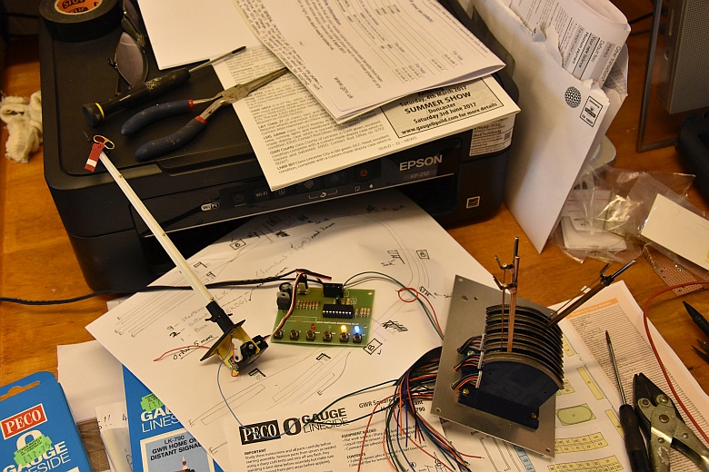
I will be using Cobalt-S
switches to control the signals, (around £16 each) and other items
such as points or LED lights in a control panel at a later stage,
but for now here is a cobbled together and working setup using one
of each of the component parts I mentioned. Each lever has 3 3way
sets of wires as it is really 3 switches in one box. For the
signals, the two wires required to connect to the controller board
are the grey and green wires in the bottom set.
 Using the furthest lever and 2 of its bottom connections, (the grey and green leads), the switch is normally set to danger. |
 Now once the switch is pulled off, it sets the signal to clear |
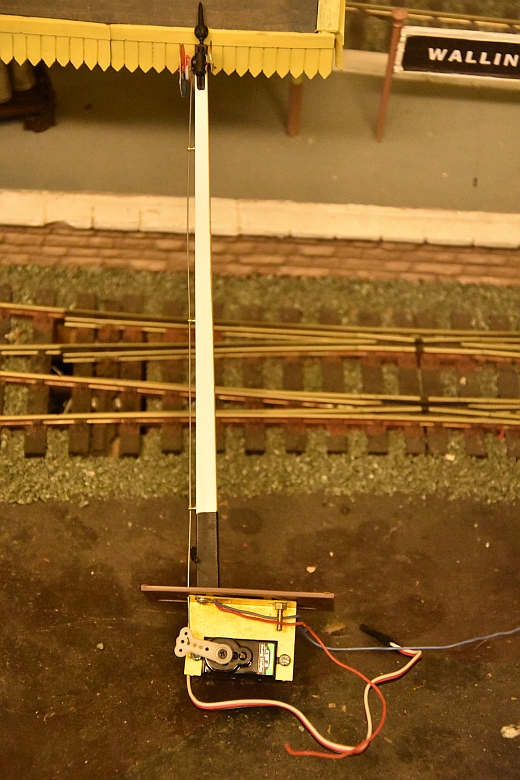
The base of the signal and
the servo bracket can be screwed together as shown below. A plate is
arranged between the signal base and the servo bracket that is big
enough to hide the ‘works’ once it is introduced into a hole in the
baseboard. The controller board is to be fixed underneath the
baseboard and the signal levers positioned onto a box that is
attached to the side of the baseboard at an appropriate position for
the number of signals it will control.
The instructions for setting up the signal are
very straightforward and easy to follow. The result is a working
signal. I’m now happy to proceed in building the necessary signals
to add some realism to my railway.
First a look at what
signals I can get away with on my railway as a minimum.
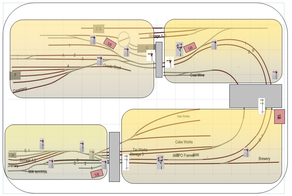
The railway is divided
into 4 distinct areas as shown below. Each separated by a tunnel or bridge. This
allows for some licence where ‘distance’ is concerned.
| The great Western had a wide variety of different types of signal semaphores. 1 shows a home semaphore, 2 the distant signal. 3 a spectacle fixed much lower due to maximum height restrictions of the illuminating lam, (30ft). 4 where this was exceeded a duplicate arm was used. 5 a shunting arm, 6 a back shunting arm, 7 start from a siding or reception line. 8 entering a siding or reception line. Great Western signals pulled off to an angle of 45 to 80 degrees | 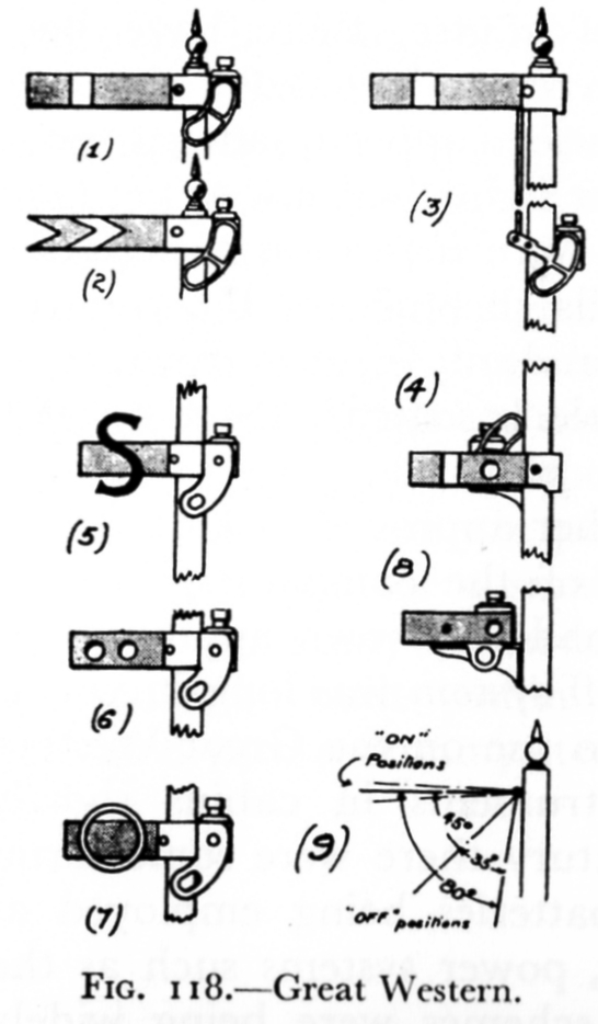 |
To see how the signals are put together Click Here.
In connecting the servo to
the base of the signal the amount of clearance between line and base
is important so I reset the servo so that its body was away from the
signal and line as shown below.
 |
 |
 |
Creating the hole can be an issue so I've started using a boring bit to create a 1.5" hole. This givers just enough clearance to site the servo and allow for its arm to move up and down.
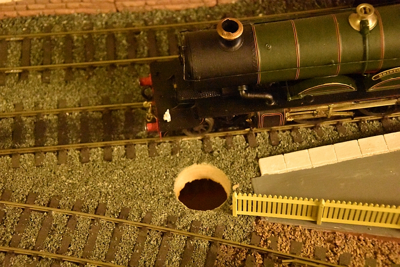
The grit is wetted and removed/scraped away and the signal can then be stuck in place once the base is dry. Any hole visible can be covered with thin paper as shown here.
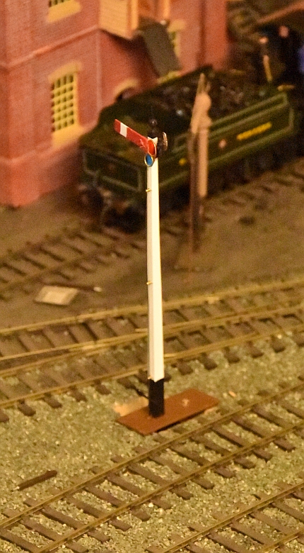
The remaining signals for the railway have now been completed. 8 wooden post signals, two with fixed distant arms to warn of possible halt at the next signal and two with rule 55 diamonds fitted. I've also modified one as it acts as a shunting signal and has a 'white hoop' attached to the arm.
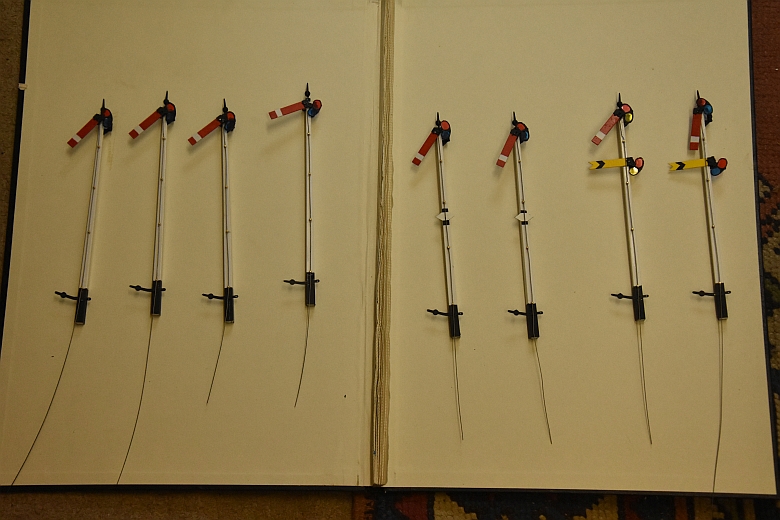
These have now been finished and fitted according to the map. The next job is to wire them up to the control levers and PCBs and adjust their movement accordingly when the levers are thrown. This is best done directly onto the PCB before committing to the baseboard. I remove the arm from the servo and switch it on. The servo will find its central position. I then reconnect the arm to the servo and adjust the throw accordingly before placing the signal back into its hole. Once I'm happy with the clerarance the signal base can be glued And finally I can grit any area around the base needing attention.
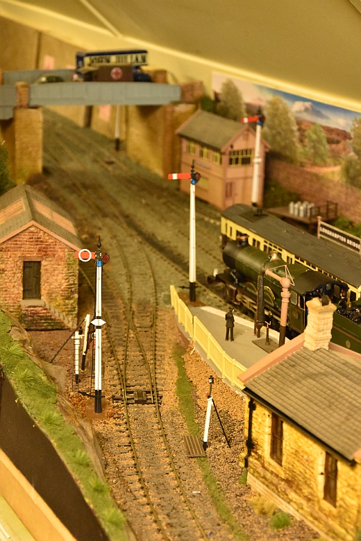
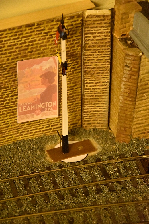
Here are three of the signals including the shunting signal in place tested and gritted.
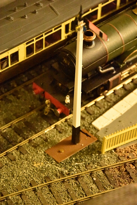
Here is a close-up of the base of one of the signals with grit applied and secured with a solution of PVA.
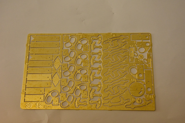
The ladder is of a soft plastic and fragile. I have decided to replace them with brass etched signals, hoops at the top and retaining bars half way up the ladder to give extra support as shown below.
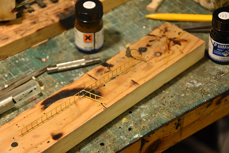
These will be painted black and glued into place against the signal post.