My O Gauge Journal on
Modelling the GWR
A personal Journey
Signalling the through station and its sidings
Converting the signals from filament bulbs to LEDs and adding a feather light signal to several for directional indication purposes. I have created a PDF file that illustrates how this is done. Click Here to view/download it.
 |
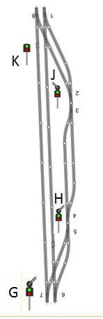 |
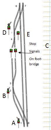
The signals required at the moment look something like this above. 6 of the signals have feather lights on top of them to show directional flow. I intend to make these from original Hornby signals and ECKON EA3 and EA4 signals. Also as previously mentioned replace the filament bulbs with LEDs.
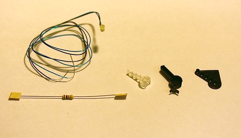
This is what EA kit looks like. A single LED fits into the clear plastic lens and this sits inside the signal casing. The whole arrangement is then super glued onto the top of the Hornby signal as shown here:
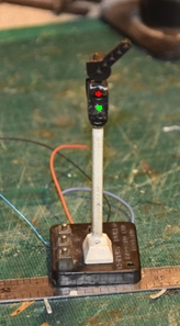
The wiring under the base is shown below. I used the existing common contact to attach the resistor for the LEDs:
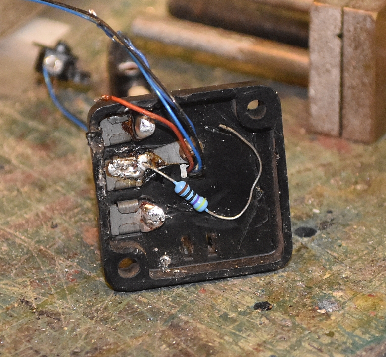
The signal now has potentially three states, (Red, Green, Green and feather)
My current thinking is that I will need two
control panels for the station and its two sidings. One for the up
line and another for the down line. There can be up to 5 possible
combinations of signals and points control for the up and the down
lines and this will entail the use of 3 wafer 6 pole switches.
Considerations for the inclusion of the use of
platforms 3 and 4 are as follows.
The rotary switch now needs to be organised so that it controls the signals and points. Here is a simple diagram of the wafers in such a switch. As the switches would normally have an even number of wafers its necessary to have a 6 pole version leaving one pole vacant, (this spare serves to be very useful as you will see later on). The numbers of the first half of the first wafer, (1-5) relate to the 5 possible positions of the switch.
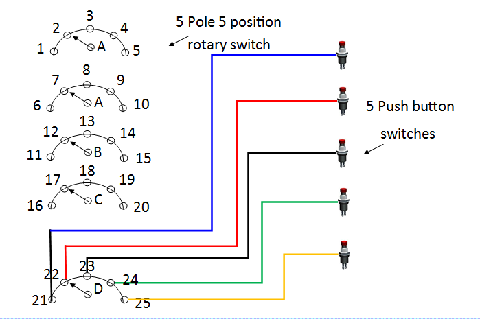
The push buttons will be used to activate the points once the signals have been set.
Hornby Dublo 3 rail
Hornby colour light signals converted to LED and with added feather signals