O Gauge Modelling on the GWR
A personal Journey
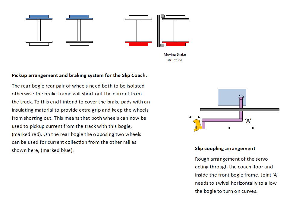
The Slip Coach:
Uncoupling and braking systems
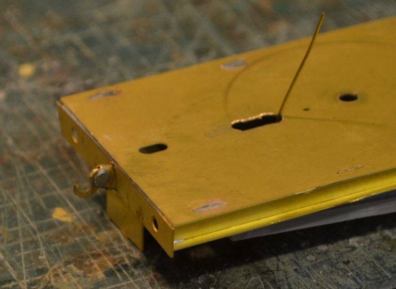
Slip Coupling Mechanism
I've looked into keeping it as simple as possible and come up with the following;
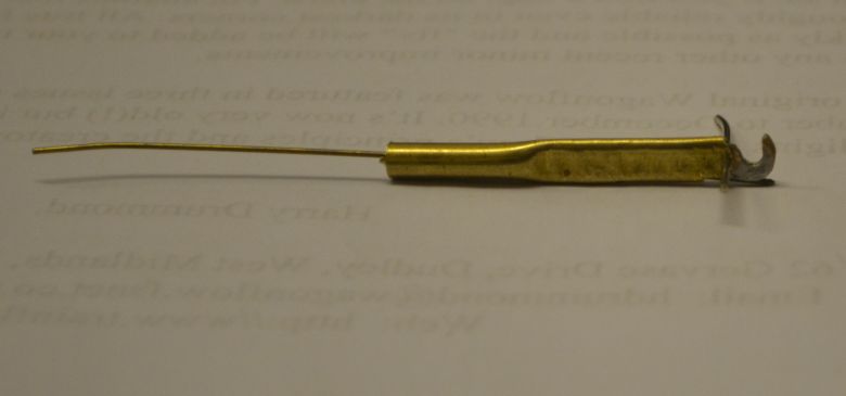
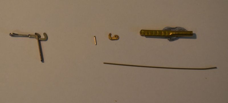
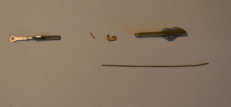
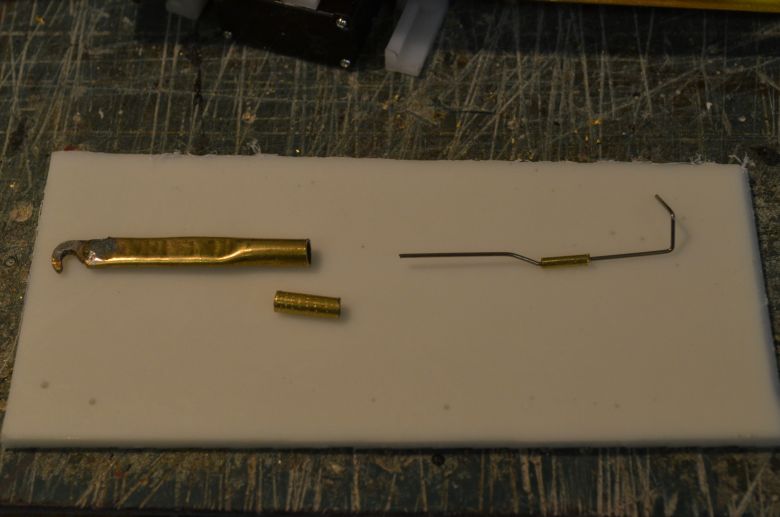
A small piece of brass tube flattened to take the front end of a brass coupling hook. The wire which fits under the hook holds it in place. With drawing it allows the hook top drop and therefore open itself. Here are the two states shown below:
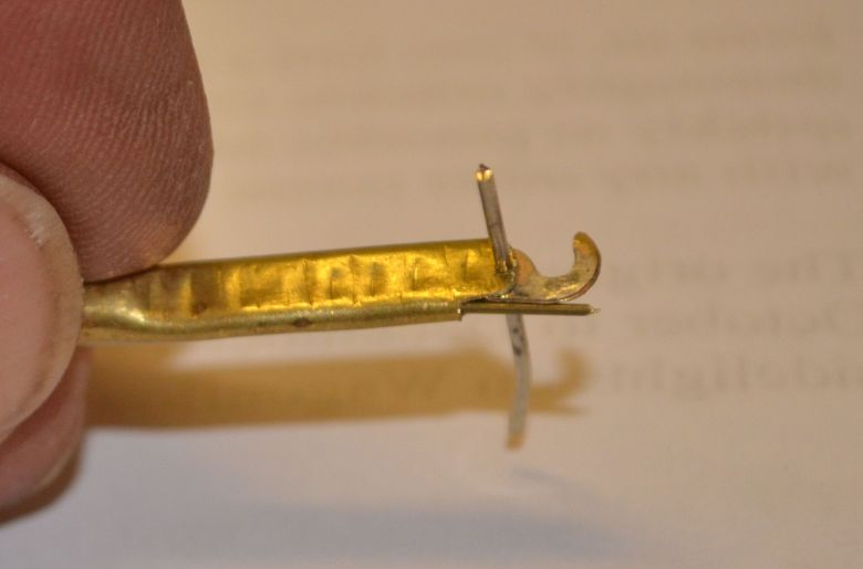
Here you can see how the rod secures the hook in place.
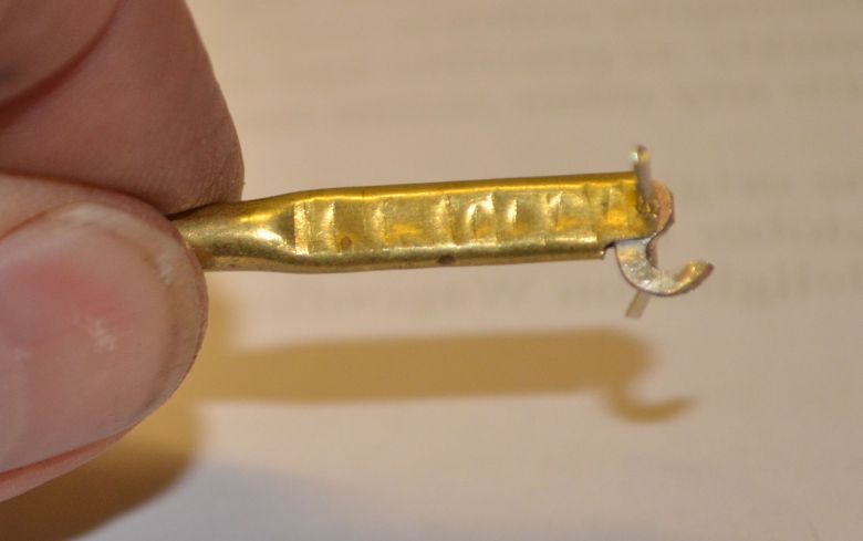
With the rod withdrawn the hook rotates on the pivot and drops down releasing the coupling. This will be controlled by a servo in the coach.
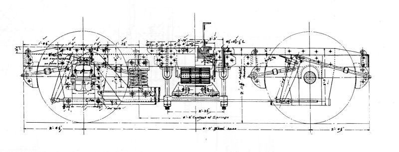
Back to the coach. I've chosen to build a single slip coach. This will make controlling easier as I can use the brake mechanism on one bogie. Here is a drawing of the particular coach in question.

More on the slip mechanism
II ordered a couple of Wayoh coupling hooks from Invertrain for the other half of the slip mechanism. They provide a rigid coupling as shown in the two images below. (Click either for a larger view).
The coupling hook needs to have a flat bottom as the rod will move forward and backwards on it to secure and free the hook which will drop away and allow the Wayoh coupling to pull apart easily.
This second view shows the slot in the pressed tube necessary to give clearance for the hook to rotate and drop away from the Wayoh link.
An important spinoff from this is my considering using this setup to allow a locomotive to automatically uncouple from its train. Any tender engine will have the space for this and I think it will be particularly useful when uncoupling and running round a coach consist in an inaccessible station terminus. DCC control boards can have servo control on them which is what I used on my travelling Post Office project. But back to this slip coach project first!
The braking system of the slip coach is also on the cards and here is a drawing of the actual system.
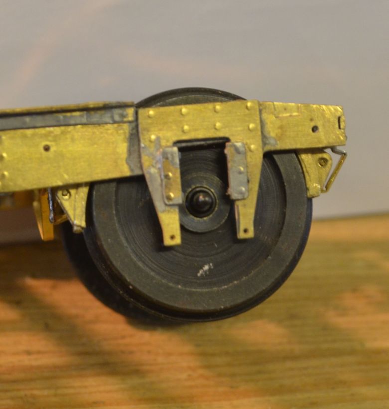
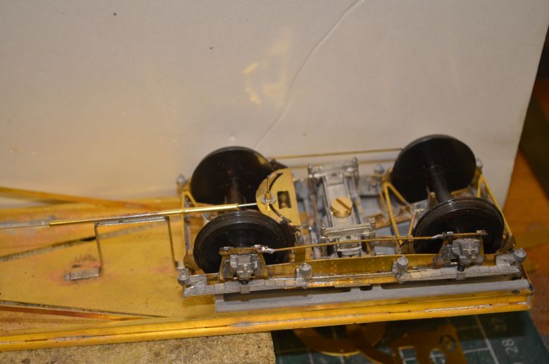
The bogie construction has gone about half way. One bogie will be made up as per the instructions with fixed brakes, the other will be a fully working brake system on the bogie. Here is the rear bogie under construction.
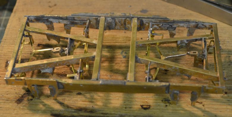
Here the braking system castings are fixed. The swivels on the brake pads are also be fixed so no movement is possible. JLTRT supplied the bogies and etches, (GWR 9' fishbelly bolster bogie PWRP2). The soldering is quite complicated but the instructions do take you through the early stages of constructing the bogie frame.
Here is the view from underneath. The axle arresters are handed but having been sent replacement ones they are all the same so I fitted them as shown, (when its all painted black and hidden underneath the coach no one will know. Some time will be spent in considering how the brakes will work on the other bogie. You can click on the above images to see larger versions.
A closer inspection of the brake linings shows
how ‘snug’ a fit they are. As this bogie will not be used for
braking, I have built it as per the instructions, and it will be the
trailing bogie of the coach. The other one will be almost the same
but with modifications to allow for some sort of braking to be
engaged onto the wheels.
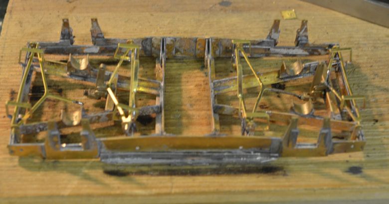
After a couple of failed attempts at using the existing framework to make the brakes here work. I have rebuilt the other bogie to incorporate a brake pair of shoes working from between the wheels as there is more room for adjustment. On the outside there is literally no room to add any leverage.
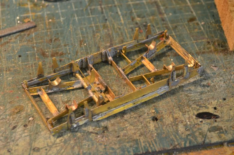
Here is the modified frame ready to have the other cosmetic brake structure added. This system will mean that the brakes will short out the current so i will be fitting pads to the brakes made of an insulating material to provide grip but more importantly, stop current passing from one wheel to the other. The central pivot of each bogie will have to be insulated with plastic pipe to avoid shorts when fitted and the screw fitting therefore will act as a feed to the control board once it is fitted. But more on that in another section on the slip coach project.
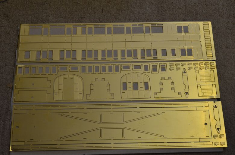
The coach body etchings have arrived. Again a great set of etching from Worsley Works. Click for a larger view.
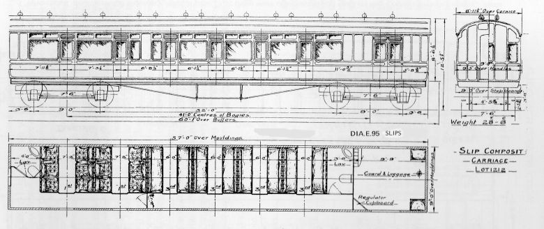
The body is based on the E95 single slip as below.
More on the chassis.
The resign chassis supplied by JLTRT I cut into three. The two outside sections are used to isolate each bogie so that i can pickup current from the rails using the 'American' method of pickup as shown here. Click on it to enlarge the writing.
Also the two outside pieces need to be 'thinned' down as they are a couple of mm too thick and this is down the hard way as follows by using a circular motion on the sandpaper bed:
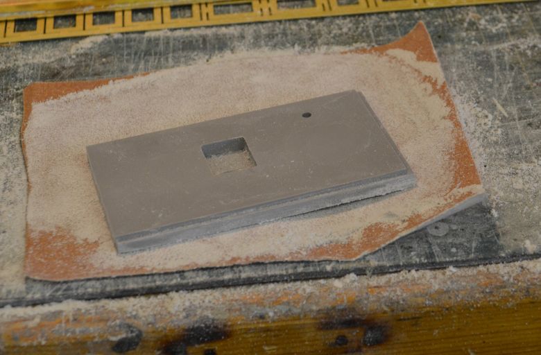
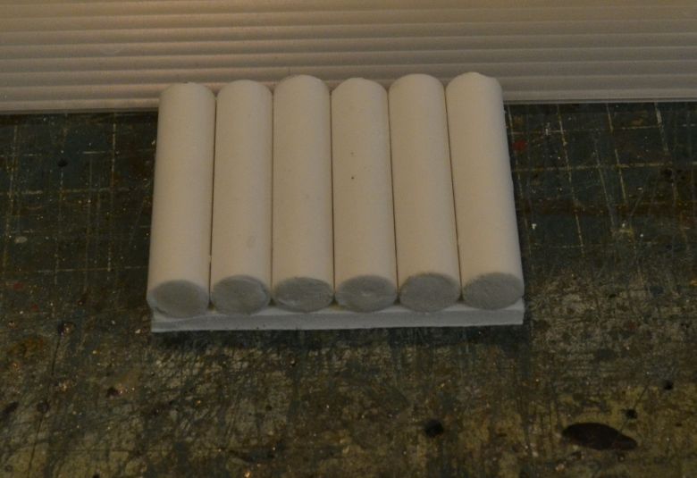
The etched chassis supplied by Worsley Works has the next stages completed, (end buffer beams support for queen posts and the vacuum cylinders are made up using plastic pipe and filled with plaster of paris to give end pieces to each cylinder and also supply more weight to the coach - especially low down!
They are glued to a piece of Polyboard and will sit between the queen posts after painting.
Back to the coupling. Having fitted the buffer beams, the end where the slot for the slip coupling is to be used needs opening out. Also the resin block needs to have a slot cut in it to accept the barrel of the coupling as shown here.
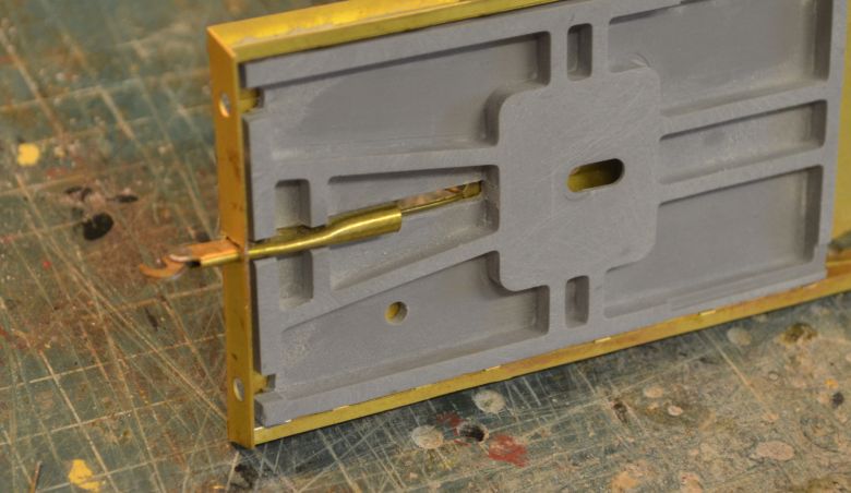
A slot needs to be cut into the brass floor to allow a rod to slide back and forwards to operate the coupling from a servo, as shown here, (click either picture to get a larger view).
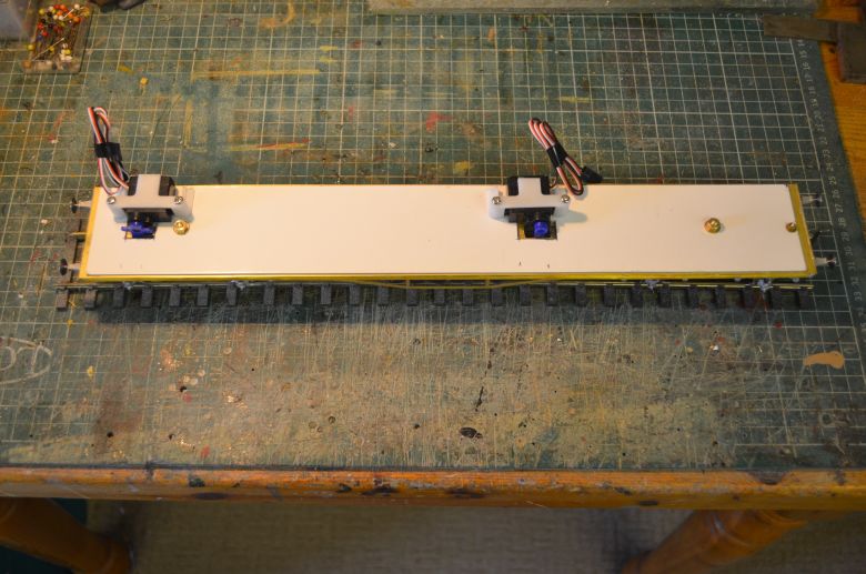
This is the current state of play but is susceptible to modification as the build progresses of course. I used ESU servo kit No. 51804 for this and the braking arrangement, (more of which later).
First issue was in placing the servo on the floor. There wasn't enough clearance to allow for the sides to fit neatly onto the floor so the slot in the floor had to be widened. The arms for the servo are all set with the flange facing inwards. This seems to be the norm whatever servos and arms you use. But it is no problem as the control rod can be off set onto the servo arm. Here is the servo as a mock-up in the widened slot. Click any picture for a larger view.
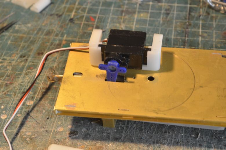
The back of the bracket that comes with the servo kit was cut off so that it was level with the back of the servo and did not protrude. This allowed for a snug fit near the edge of the floor without fouling the coach side. The underneath arrangement now looks like this:
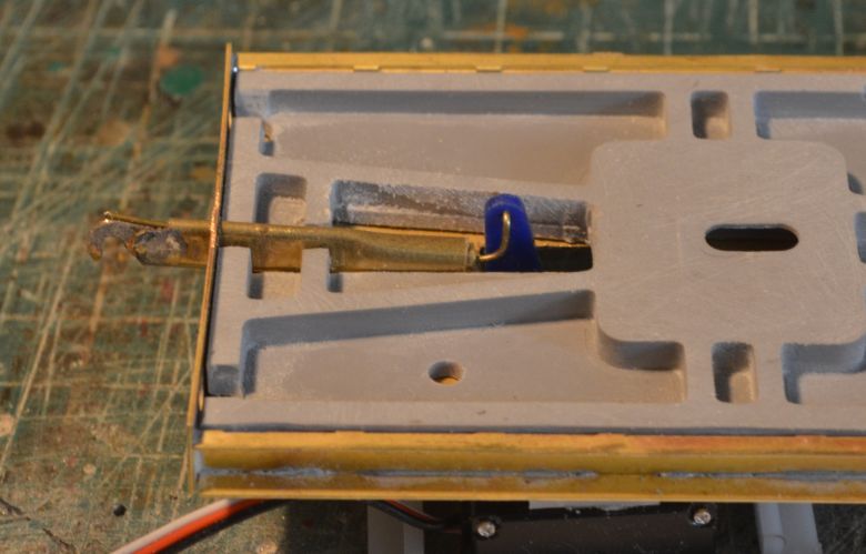
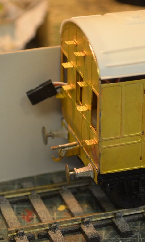
To allow for smooth working of the control rod I used the wire included with the kit. In this picture a brass wire is in use as a tryout. The final arrangement is shown below. I have created a double filled channel using progressively smaller pieces of brass tube to support the rodding and sculpted it as shown below.
The kink in the wire aligns it with the bottom of the coupling hook and makes for a smooth traverse in catching or releasing the hook.
At the braked bogie, I have created a sliding frame to allow the bogie to rotate whilst still allowing the brake to be used, (and of course to traverse curves when not in use!). Here is a mock up of the arrangement. Its important to isolate the rodding support from the chassis or it will carry current across the slip coupling and the coupling at the other end of the carriage chassis. I used epoxy resin and coated the frame first and then glued the pipe to the frame with more resin. Hopefully this provides enough strength to keep it in place and stop any current getting to the chassis.
This arrangement will allow the bogie to rotate a few degrees either way. Click the picture to see more detail. Also as per my reference to alterations earlier, I have replaced the cast brake shoes with plastic ones from Slaters, (7159A), to ensure no electrical shorts across the wheels when I introduce control through the DCC system I use.
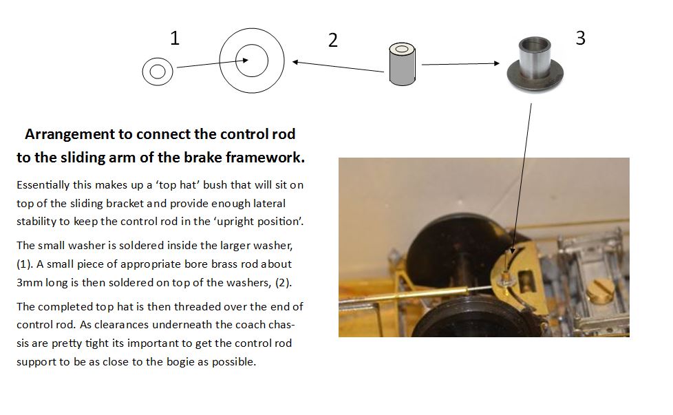
The method I'm trialling to connect the control rod to the braking arrangement is as follows in more detail: (click on the image for a clearer view). I soldered a small disk beneath this arrangement to add more stability to the movement of the rod through the curved slot as well.
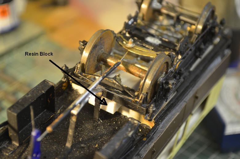
Something that has come to light in trialling the mechanism is that it encourages the bogie to rotate about its pivot point in an upward direction. This has the effect of lifting the wheels used for braking off the track! To counteract this I have inserted a block of resin to allow the bogie to press against this when the brake is applied, as shown here.
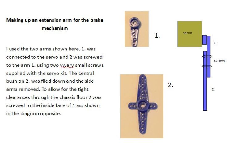
The rotating arm from the servo needed to be extended and this was accomplished as follows: (click for a larger view).
A card base has been glued to the floor and the servos screwed into place.
Thorough checks follow to make sure that the chassis and bogies are isolated from one another. The swivel screws protruding through the floor will be the connections for the pickup current from the rails as identified before and must be completely isolated (using plastic pipe of an appropriate size). I then check with a multi metre that there is no leak anywhere and test by running on the railway behind a loco looking for any trace of sparks or overloading!
The coupling system does have a flaw in that certain couplings will jump the hook so I have put an extra securing pin over the hook, (not unlike the real structure that secures the hook from above as opposed to mine which is secured from below as shown here:
The above video clearly shows how the coupling will work.
I am still having issues with the bogies shorting out. This is mainly due to the axle boxes having too much play in them and also twisting in the slides. If I had not used Haywood wheels it might have been a better option. Haywood wheels are metal throughout with insulation on the axle. This means that the central boss surrounding the axle which sits proud can connect with the axle boxes. The likelihood of this happening is multiplied by 4 as both bogies are used for current pickup. Add into this the fact that the brake shoes sit too close to the wheel rims and do not have enough room to be moved outward adds to the situation. Multiple shorting is not good for DCC and I'm considering replacing the wheels with Slaters ones. The same ones I used on the TPO which gives no problems what so ever.
As you can see above, I have now replaced the wheels with Slaters Maunsel disk GWR wheels and shorting has disappeared!
Here is the first brake trial