O Gauge Modelling on the GWR
A personal Journey
The Slip Coach 2:
DCC control of the coach
The main control aspects for this project are as follows:
A servo that controls the coupling system
A servo that controls the braking system
A warning bell on the front of the coach
Internal lights
A couple of rear lights
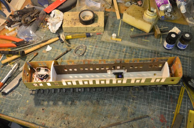
Here is an internal view of the coach showing the two servos in position and partitions for the corridor and guards and toilet ends of the coach. It is envisaged that the control board will be housed in the guards compartment. Click the image for a larger view.
It is possible to have control organised in a variety of ways from the control board. Namely,
-
Press for ON, Press again for OFF
-
Press and hold for ON, Let go for OFF
For the uncoupling system and lights, I would use option 1, For the braking system and Bell I would use option 2.
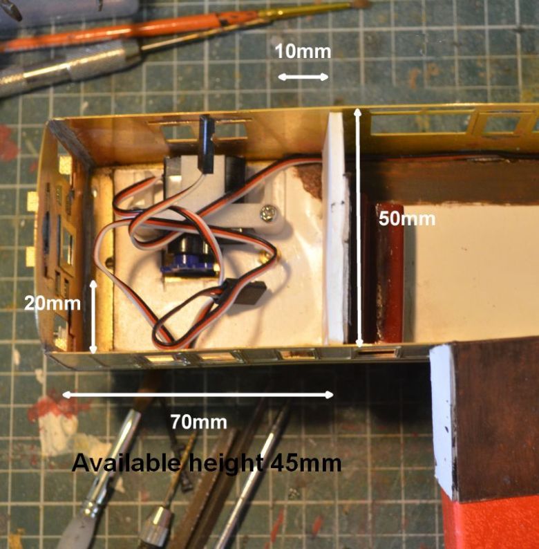
Here is a close-up of the guards compartment where I will store the control board. I have two options for control, (both by ESU available from Coastal DCC, (link top right of this page). I could use a standard 21pin Loksound decoder along with the I/O extension board or a single XL board which is more expensive, but it really comes down to available space.
The bell sound is something of a mystery but I have found that it is similar to the autocoach setup. This picture shows the arrangement of a foot pedal that activates the bell.
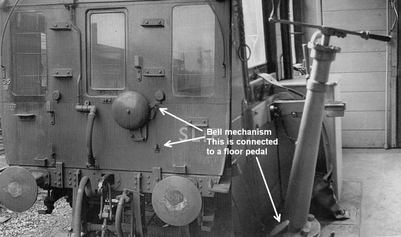
Its a rather simple arrangement giving off a single beat and not a continuous ring. Probably used to give warning of its approach with no more than one or two presses of the foot pedal. Click the image for a larger view.
To reiterate, the DCC programming necessary now follows:
In the slip coach are two servos. One to control the coupling
device, the other to activate the braking system on the rear bogie.
There are a number of changes to make to certain CV settings as
follows:
CV31 should be set to 16, CV32 should be set to 0.
The mode setting for AUX 7 which is CV 323 is 27.
The mode setting for AUX 8 which is CV 331 is 27
Setting AUX 7 to be controlled from F1, the following CVs and
settings were applied:
CV 326 is the speed of the servo, (the lower the number the faster
the servo rotates)
CV 327 is the start position of the servo
CV 328 is the finish position of the servo
I started with: CV 326 = 10, CV 327 = 36, CV 328 = 28 (an
anticlockwise turn of about 5 degrees)
(the range of the CVs is
0-62 ).
For AUX 8 to be controlled by F2, the following CVs and settings
were applied,
CV 334 is the speed of the servo, (the lower the number the faster
the servo rotates)
CV 335 is the start position of the servo
CV 336 is the end position of the servo
I started with: CV 334 = 10, CV 335 = 28, CV 336 = 18, (an
anticlockwise turn of about 10 degrees)
(the range of the CVs is
0-62).
Again a
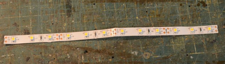
I've put in some LED strip lighting in the coach roof to illuminate
the compartments. This is a strip LED of lights with inbuilt
resistors from
CRT Kits.
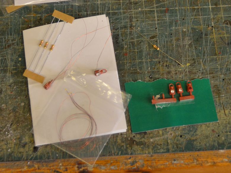
And also two warning lamps at the rear of the coach
The micro LEDs I used to fuel the lamps came from
www. expressmodels.co.uk
and they really are very small! I drilled through the lamps
with a 0.3mm drill inserted the LEDs, (they come attached to
insulated wires), filed off the back of the gem and re fitted it
with superglue so that the LED would shine through.
The final
part of this section
was to set up the CV values to make the lights come on using
function 0 on the controller. This was done as follows:
Connect the lighting circuit to the headlight terminal and the
common return terminal(+).
The function F0 would be made to light lamps and interior lights in
both forward and reverse directions so the CVs to set are as
follows:
Set CV31 = 16 and CV32 = 1
Then set CV282 = 1
To alter the brightness of the LEDs
Set CV 31 = 16 and CV32 = 0
Set CV 262 = 1
Then set CV 262 to 3 (Value
between 0 & 31, where 31 is the brightest )
The arrangement in the coach now looks like this, (click for a larger view):
In the guards compartment is the control board a loudspeaker unit and a servo to work the uncoupling device. In the main carriage compartment is the servo situated centrally to work the braking system. In the toilet compartment on the right is the small board that connects to the two warning lights on the rear of the coach. Glued to the inside of the roof is the LED strip that will light up the coach.
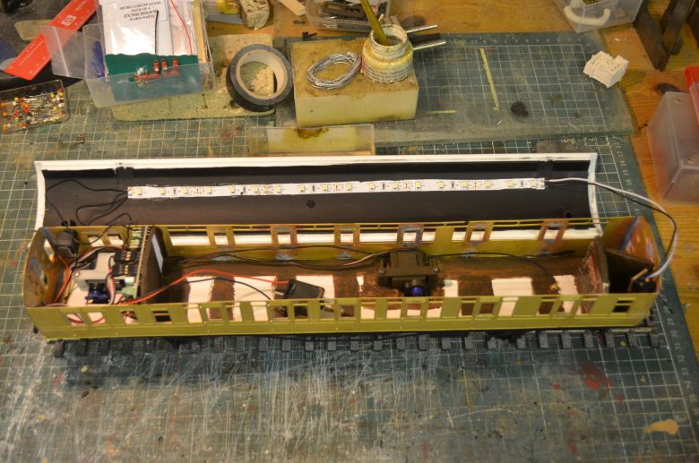
The electric motor is only there to provide resistance and something to enable CV programming to take place on this card, (ESU Loksound 4XL). It will be removed once programming is finished. I could have gone for a cheaper option to control the coach but not having to solder the servo leads to it makes for an easier life plus all my other locos etc have the same cards in!