O Gauge Modelling on the GWR
A personal Journey
Electrification of points and control of signals
The electric points are a boon in difficult places to reach and make working the layout much easier. I'm still unsure about signals as the colour light signals work independently of the points and I would like them to be integral. That would mean me loosing a whole bank of switches. But there are issues with controlling solenoids and constant light bulbs together as one item which is what I'm looking at. The options seem to be:-
-
using a control board with a latching relay that will do the job, (haven't found anyone yet who makes one at reasonable cost).
-
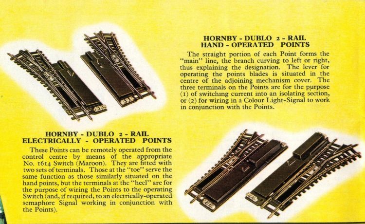
Using an old point of the 2 rail variety below the baseboard connected in parallel to work the signal, (the type needed have two sets of three terminals on them but there are electric and manual versions out there as shown below - I'm still trying to gab one to try out)
-
Give in and swap all your electric colour light signals for electric semaphore ones, ( not a cheap option as I have 15 single home signals and 4 doubles currently). Not all the signals are in the right places now due to modifications of track and there are important ones missing and some that shouldn't/needn't be there.
-
Don't bother with any signals at all!
The last option isn't really what I'm about. So I'm investigating options 2 and 3 currently.
Having purchased a 2 rail point. AND the correct one with two sets of connections as shown above ( image on the right hand side of the illustration) here it is with the switch casing removed:-
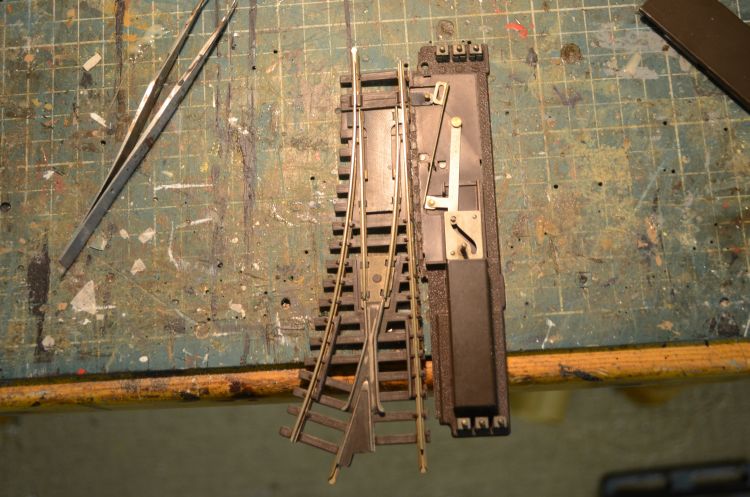
Cutting off the point which isn't needed is relatively easy with a Dremel wheel. (apologies to the 2 rail fraternity).
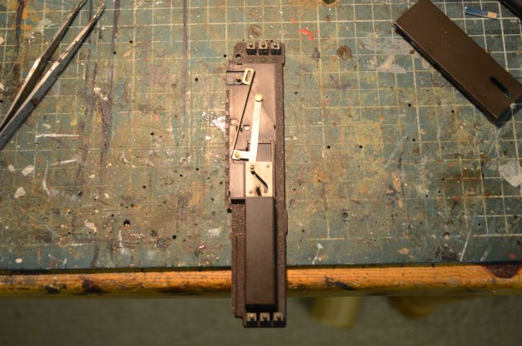
Be careful to glue the latch that moved the point blades to the base and make sure the long arm with the slot fits on the pin, (as shown above it isn't on the pin!). This will ensure that the switch works properly, (there are two small contacts halfway down the arm that are used as the on/on switching facility.
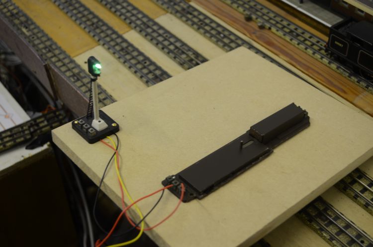
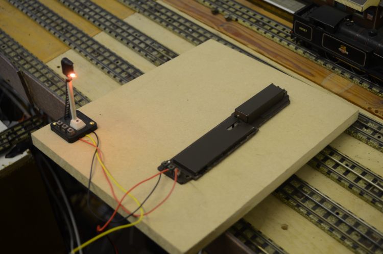
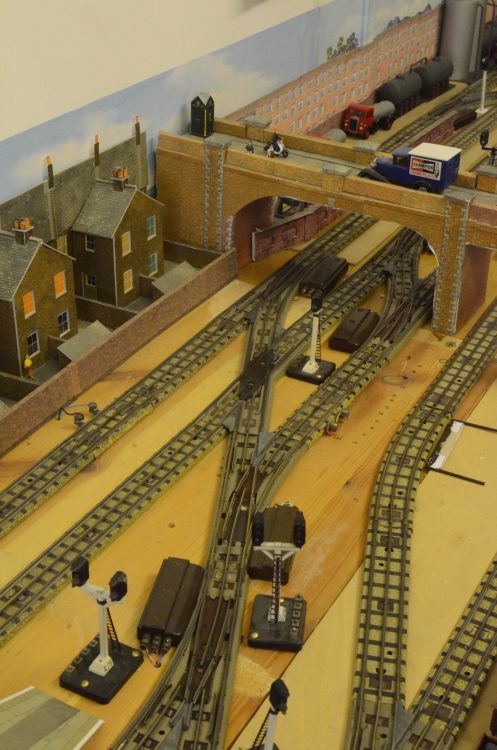
Here i am testing the switch having tested the solenoid. all that remains now is to wire this in parallel with the point on the baseboard. I am going to create a vertical control board to fit several of these modified points to control several lights on the layout. First though I am going to set up three signals to work with one point as shown here:
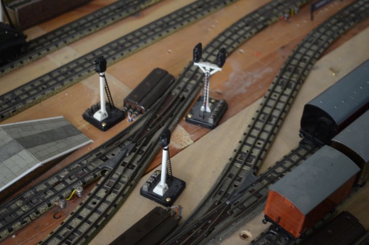
Here we have a single starting signal next to the platform, a shunting signal and in the other direction a double signal to control main and branch lines. Currently 4 switches are used to control this part of the layout, if my information is correct I can reduce this down to one switch. Here is the wiring diagram:
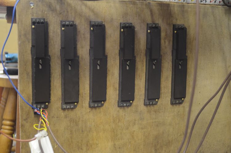
Here is the board with the first solenoid and switch in position
And it worked first time. All the lights show the right colour for each road both ways.
I now have 5 more that are in place ready to be used.
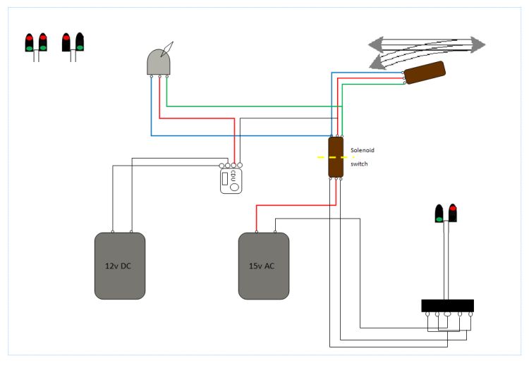
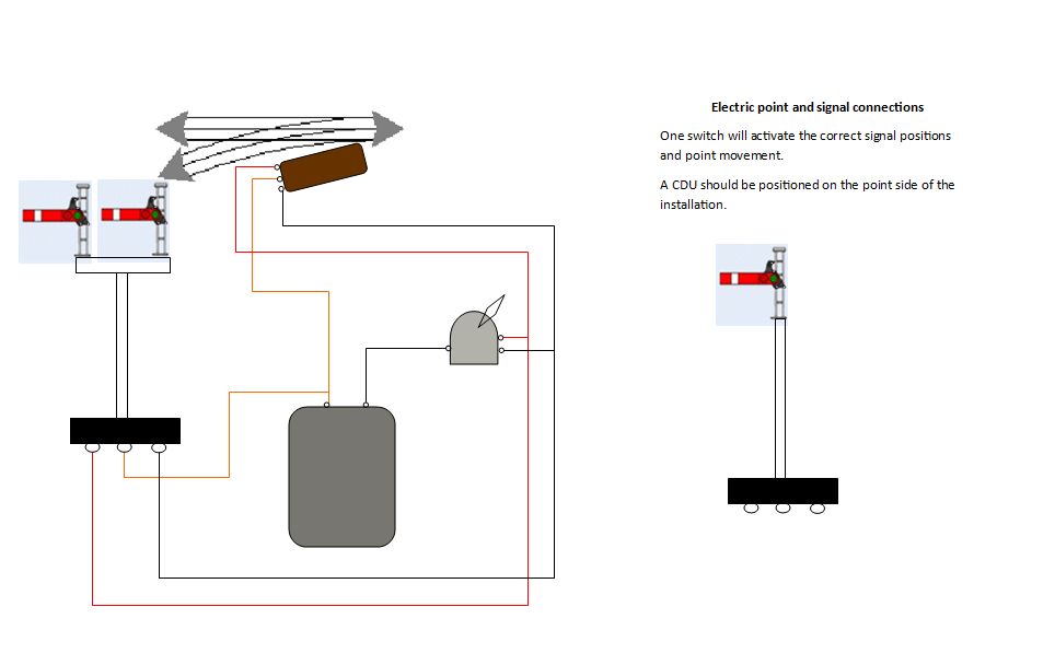
How to connect signals to points so that they show the road open automatically is not strictly prototypical but does lend itself to more correct operation. The main issue with colour light signals is that they require a constant supply of power whereas electric points only want it momentarily. This means that the two cannot be directly connected together. However if semaphore signals are used as they both use solenoids to operate they can be connected together. So what to do if the former are involved. Here are some wiring diagrams:
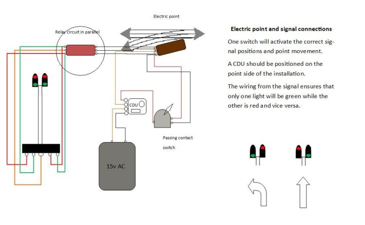
The diagram below is slightly wrong as there should be 5 cables coming from the signal base as with the diagram below that but I've left it as is for clarity. The wiring would be correct for a single double light signal.
In upgrading to electric points. I came across the Hornby leaflet that shows how a signal and point can be activated by one switch. (both solenoids). Colour light signals will require other considerations which I am investigating. Here is the corrected layout with the addition of a CDU:
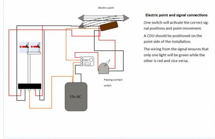
To connect a colour light signal an intervening 'box' will be required. This can be as simple as an old 2 rail electric point motor with switch or a transistorised Latched relay circuit.
Electrifying points
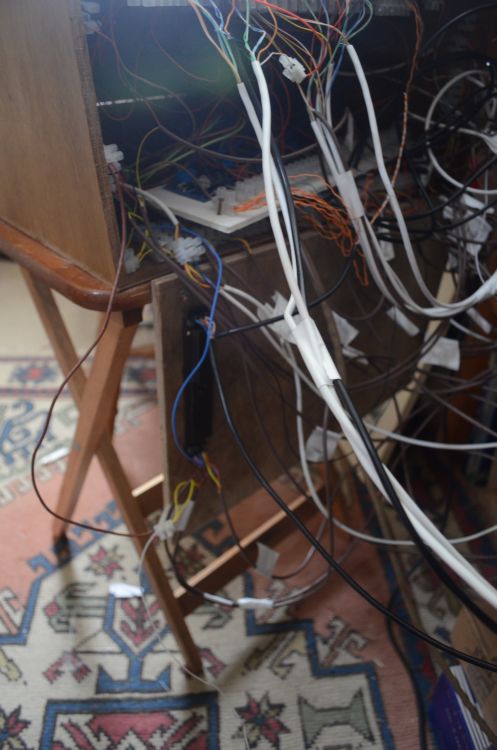
some interesting issues with these old setups