My O Gauge Journal on
Modelling the GWR
A personal Journey
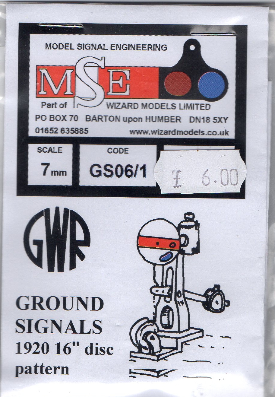
Ground Signals
To finish off the signalling I thought of those small disc signals you see by the side of tracks and how good it would be if my railway had some. But is this another can of worms I'm about to open I ask myself?
The starting point was the purchase of the signals themselves. I already had a couple of 'cosmetic' ones in the first section of my railway but wanted working ones for the sidings in the fourth section.
I started looking at how I would install ground
signals in this section thinking that they were just a different
type of signal doing the same sort of thing that home and distant
signals do. But it soon became apparent when reading up on them (and
dare I say it), asking for help on forums, that they were anything
but.
Having taken onboard advice and
digested published
material describing their use into consideration, my thinking has
moved on to the extent that I see ground signals as multipurpose and
now not in the same sense as ‘normal’ signals. To be specific for my
purposes, I wanted to use them purely in conjunction with shunting
activities.
Michael Vanns book on
‘Signalling in the age of
steam’, on page 50, talks about ground signals as being part of the
family of ‘subsidiary’ signals. This group of signals would often be
alternatives to the standard type of semaphore signal placed on a
pole. Their job; to work in places where using ‘running signals’
would not be appropriate. So no change of use there!
By the 1880’s more use was being made of
‘subsidiary signals’ to control shunting movements as well. Like
running signals though they could only give one of two indications
at any one time but the ……. Terminology used to describe them
differed according to the individual companies employing them.
By this, I take it to mean that usage varied.
For instance if used in a calling on situation it would only
indicate to the driver that the line was clear to a certain point
and no further or in the case of a platform being involved a train
could enter it with caution even if it was occupied by another train
ahead. But to use his words in particular about Ground Signals this
was ‘’where most variety was evident’. Even to the extent of what
they were called. ‘Dollies’, ‘dummies’ and even their design was not
to any particular standard. So, I was still not clear as to how I
would be using them.
Turning to Adrian Vaughan’s book ‘A Pictorial
Record of Great Western Signalling’, he describes how in a sense
they started out as direction indicators like normal signals but
used in restricted situations and as such had limitations as to use.
To make sure that safety in use was maintained, they wouldn’t be
connected directly to points because if they were, they could only
give a proceed aspect according to the way points were set properly.
But, to keep it within safety limits they would only be interlocked
to points by means of a locking plunger that made sure that they
could only be worked from a signal box by a separate lever and could
only show route, if the points were set correctly. So, the ground
signal here still seemed as functioning to show the road.
Sifting through numerous pictures and plans of
station and siding arrangements with the odd ground signal in them
showed that there were two distinct situations where a ground signal
could, (although not always), be used. When leaving a main line to
enter a siding or re-entering the mainline from a siding. The ground
signal would be interlocked with points but its movement is
controlled separately from a ‘signal box’. This was not to be found
in every case though and where you would expect a ground signal to
be in use often there was none, and vice versa. This has given rise
to the notion that ground signals are non prescriptive and do and
don’t appear according to some formulae that is unknown!
Finally, it is common for them to be used in
conjunction with a human element namely in the form of the shunter.
Engine movements where ground signals are to be found are slow. They
are often under the control of the shunter with his pole and often
in situations where points are operated by ground frames there would
be no signal.
Shunting
Signals.
These are used to control shunting movements within station
limits including movements through crossover points and into and out
of sidings. The purpose of this is to allow an engine to perform
movements not normally allowed by running signals, because shunting
movements are undertaken at low speeds the signals are normally
placed on small posts on the ground as there is no need for them to
be seen from a far. GWR shunting signals started life originally
much like a small version of normal semaphore signals. Eventually
these were replaced with a white disc with a red stripe painted
centrally horizontally across it. The disk was rotated through 45°
to show a clear aspect.
In sidings where a head shunt was provided
there would often be found a different type of ground signal. This
one known as a “Yellow Disc” took the same form as the normal discs
but had a yellow stripe painted on them instead of red. The purpose
of this type of signal was to allow a train to pass at danger
providing the route was set for the head shunt and not onto the main
line. This enabled shunting to proceed in and out of sidings and
into the head shunt without the signalman having to clear the
shunting signal each time.
Bearing all this in mind,
and suffering from information overload, this is what I have
decided to do. On the fourth section of my railway where the branch
line is and several sidings are used for storage and access to the
malt house I will put my working ground signals. They will be operated by
levers akin to the nearest signal box setup, (I don’t at this time have
interlocking installed on the railway so it will be assumed that is
taken care of or in my book 'fudged'- So how will this be 'fudged'?
The points are CDU controlled and snap to attention when
asked, the signals on the other hand can be slowed down so that it
appears that they only change after the
points have been set properly - da da!). Not all sidings on my railway have ground signals as
they would
in reality. I will use this one area to install working ground
signals and the project will investigate how best to achieve this.
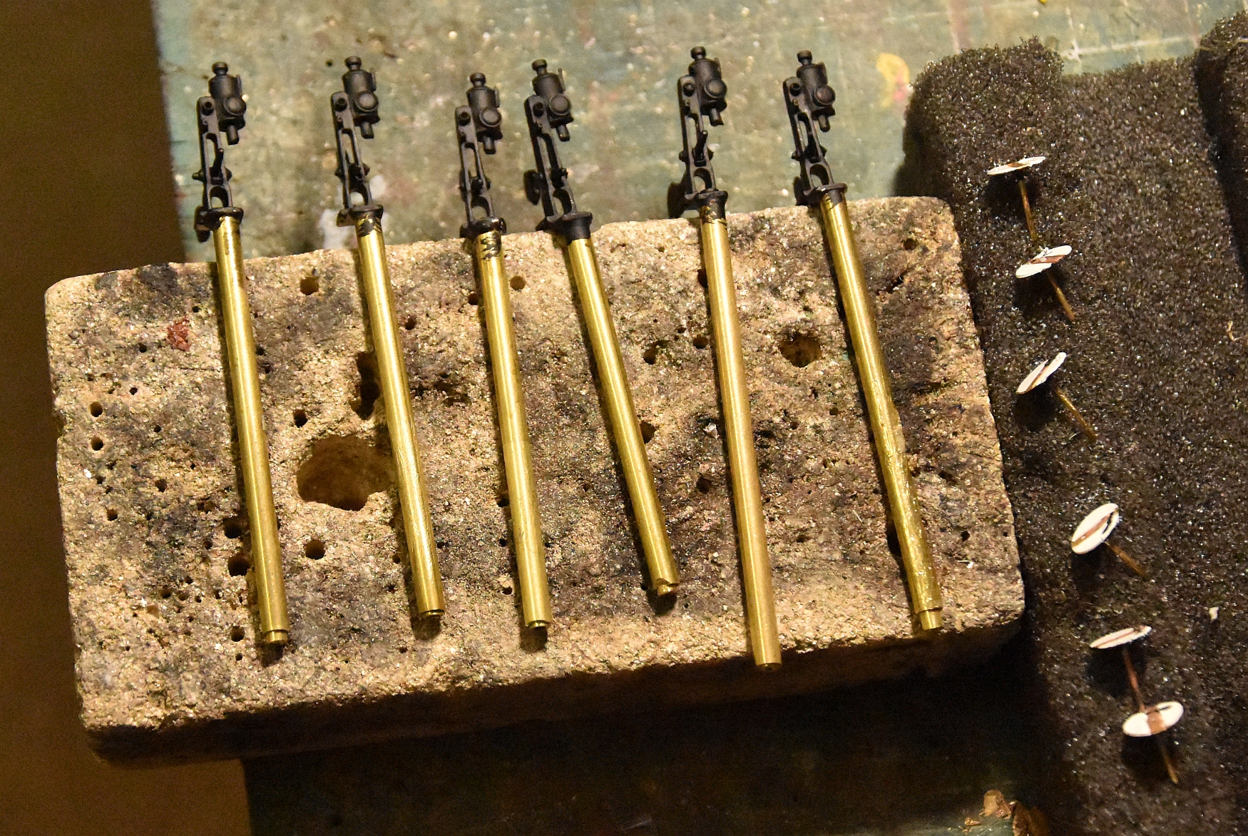
The MSE ground signals have been glued to a brass pipe base as shown above. The 'pipe' consists of three pipes the smallest will take the wire from the signal to the servo. I've left the length far in excess as to what will be needed for now, but they will be trimmed to the thickness of the baseboards. Click the image to enlarge it.
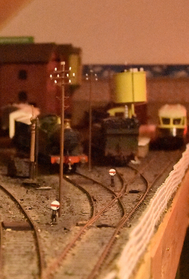
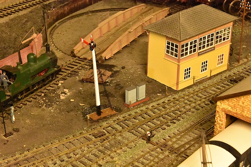
Here are a couple just slotted into their holes but far from finished!
At the same time I experimented with cosmetic point rodding and signal wire pulley posts. This is the result:
click either image to see it enlarged
And to finish off the details, i have added relay and electrical boxes near each signal box and signal.
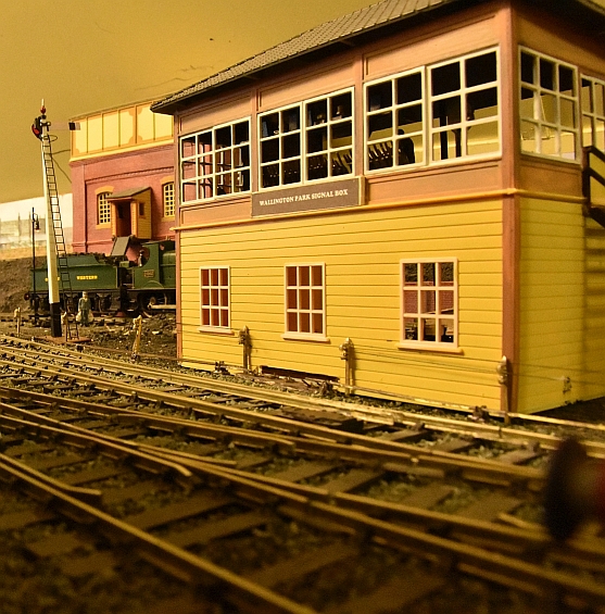
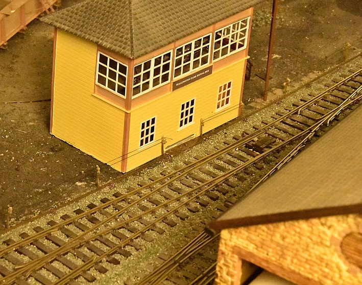
I have decided to add another signal box to control the ground signals. A suitable place is shown below.
The amount of rotational movement with ground signal discs is minimal and this has proved to be difficult to maintain. Even with the brass piping the amount a servo has to rotate is very small. With hindsight I would have made a brass sleeve for the disc to rotate in as well. The smoothest of movement is key to the success of a signal working properly.
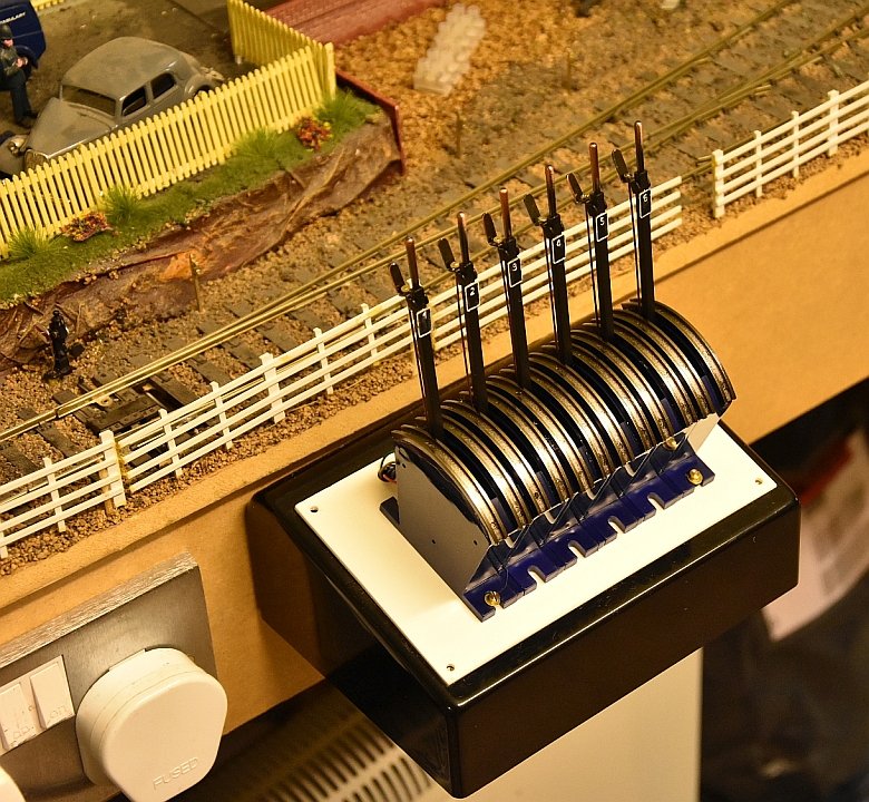
Another development with these ground signals is the change in activating the points as mentioned before. I am converting the switch bank so that the Cobalt-S switches work the points as well. this will do away with the PECO switches I have used previously. All the switches below will be redundant.
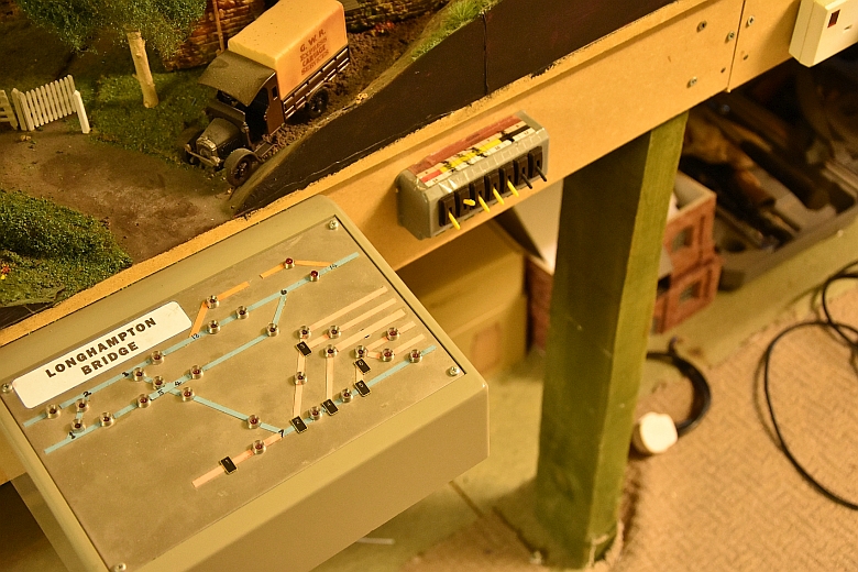
To be replaced by these now working both points and signals.
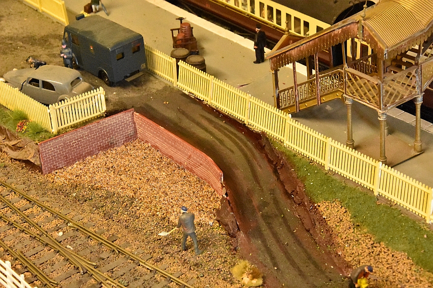
A final double ground signal is to be installed at the far end of Longhampton Bridge platform, to control running round activities.

This will require a double servo control board, two servos and brackets and two more lever switches all housed in a small control box.
The final touches are shown above with a cobalt-s switch controlling both signal and point.