O Gauge Modelling on the GWR
A personal Journey
Signal Control
How to do this in the most straight forward way possible has been a cause of much head scratching. But here are my first thoughts on it.
 |
 |
More detail here on how to accomplish this. Click the picture for a larger image.
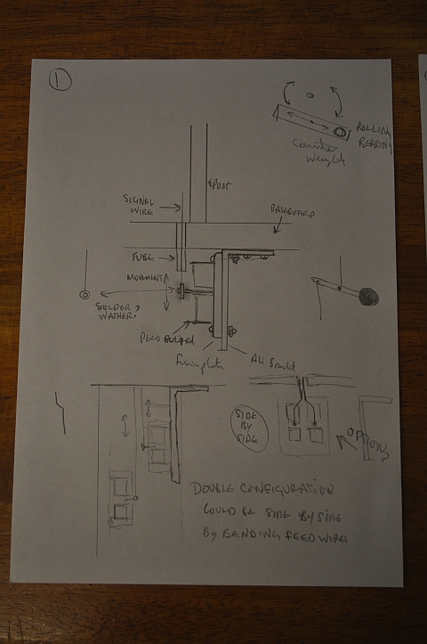
The control of signals can be achieved in it most simplest form using a tortoise control motor.
Assemble the signal in the normal way with the operating wire (brass
or nickel-silver, not piano wire) passing straight through the
signal base with about two inches of wire projecting below the base
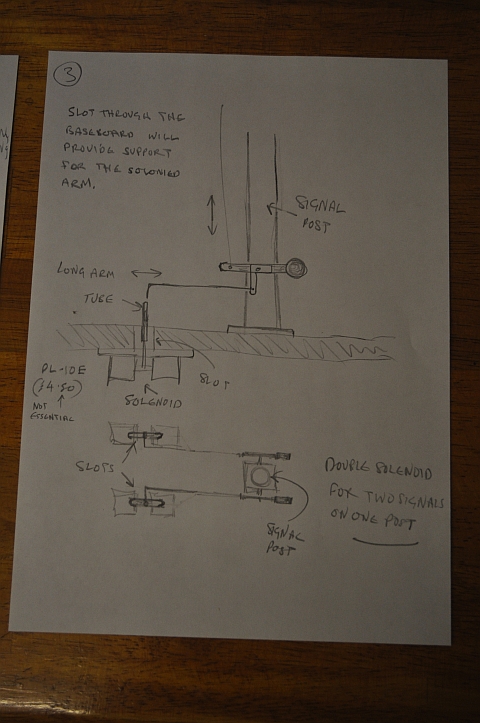
board. its good to have a brass tube extend down through the
baseboard to give extra support to the control wire as shown here.
Assemble a Tortoise point motor as per its instructions and
mount it on a piece of thin plywood at right angles under the base
board so that the Tortoise wire operates up and down, just
touching the signal wire at right angles and projecting roughly half
an inch beyond it. Solder a small washer to the signal wire so that
the Tortoise wire passes freely through it. Wire up the
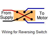
Tortoise through a dpdt switch.
The wiring diagram for the dtdp switch is as follows:
Once working, you can adjust the throw of the Tortoise wire
using the plastic slider. Once set up, you should have a reliable
and maintenance free mechanism. The built-in micro switches on the
Tortoise can be used to operate LEDs or to isolate a section
of track to stop a train when the signal is at danger.
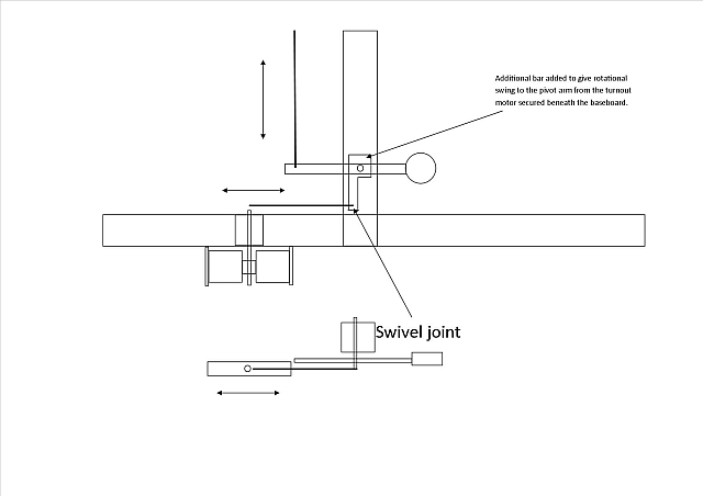
The above method may not be accurate enough so i have adapted the motor as follows:
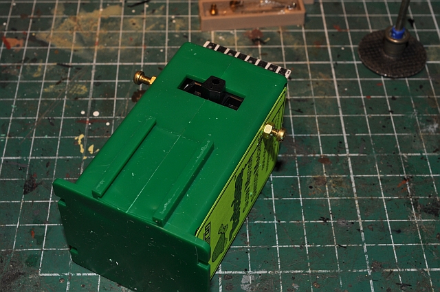
I drilled and tapped two holes in each side of the motor. You can
see that the holes are opposite the black arm that moves across
projecting through the slot. There is enough room to use a 6BA bolt with
a lock nut to hold it securely. You will then be able to adjust the
'throw' of the black arm by screwing in or out each bolt. This does away
with levers etc and coupled to the above method will produce a more
accurate control. This won't harm the motor as it moves under constant
supply voltage until it stalls against each bolt. In effect you are just
making the slot smaller etc. Leave yourself enough room to rotate the
'top' bolt and then secure it using the lock nut and a small spanner.
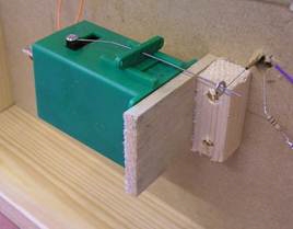
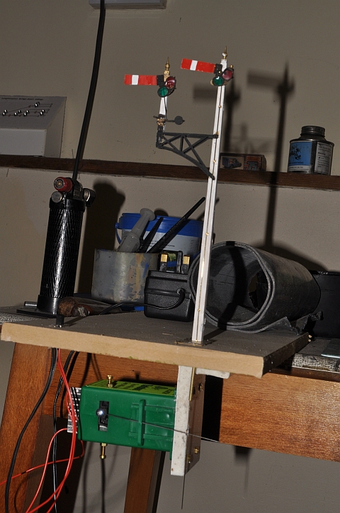
I will be setting up a trial system soon to see how accurate this
actually is. And here it is below. One issue the arm needs to be
more secure as its a little floppy at the moment, (was my first
attempt at building a signal). Consequently, the wire is only of
brass and bends easily under pressure. I have ordered some piano
wire to see if that improves the situation
| . To make the piano wire work efficiently requires that you first make a loop in the wire, (this is much easier than trying to solder a washer to it), then thread it up through the bottom of the signal through the supporting pins in the post and finally connect it to the arm by bending the end through 90 degrees. Final adjustment takes place using the screws in the tortoise unit. See the video below for the end result. 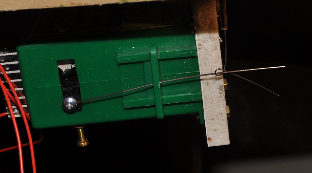 |
Signals
A control system