O Gauge Modelling on the GWR
A personal Journey
New bay at Longhampton bridge
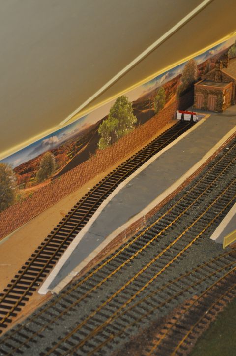
Due to congestion experienced at the station throat and the halt at the end of the spur, it has been decided to redesign the platform on the up line side platform to accommodate a bay long enough for a steam railmotor or 0-4-2 with a single coach.
I have incorporated this project into a short film below that also shows the recent addition of a level crossing control system further down the line.
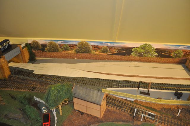
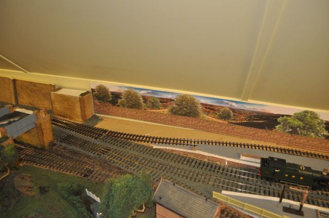
The turnout will be placed just under the bridge as this paper pattern shows.
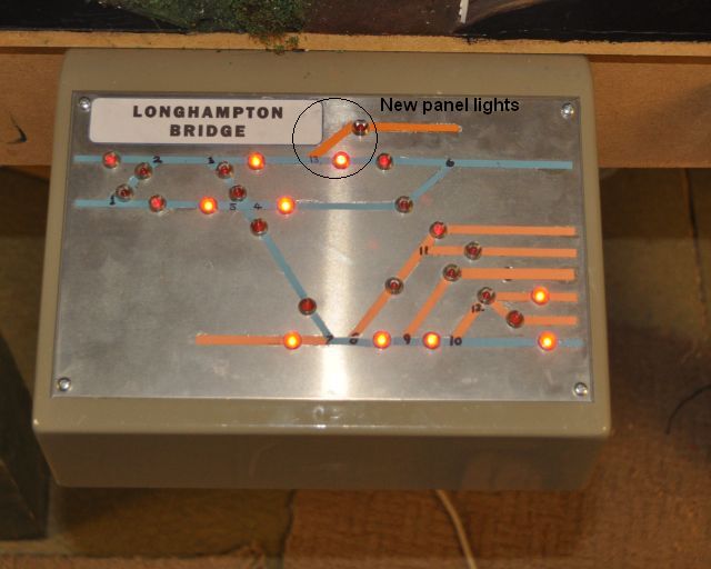
Adjustments will have to be made to the signal box control lights and electrics but that should not prove to be too difficult.
The programme of events are as follows:
Redesign the area using a paper template, (see image above)
Resculpture the platform to accept the new siding.
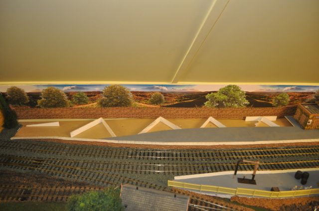
I cut away the rear section of the platform and removed the platform supports.
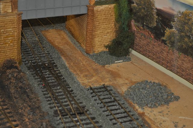
Soaked the ballast and platform edging where it was glued to the baseboard. Then removed three sections and re-sited the ramp as shown above. I have some platform edging but have ordered more from Invertrain to complete the conversion.
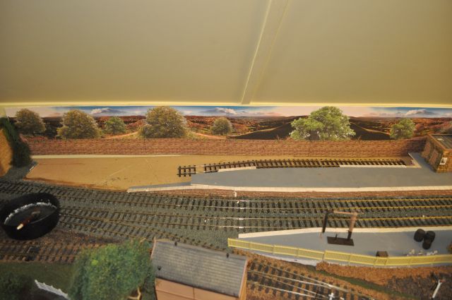
Cut out the old rail and insert the new turnout. Soak the railbed well with water to soften the PVA holding the granite chips in place. As i wasn't too fussy about this section of rail after a soaking it was pulled away from the baseboard to make removing the granite easier.
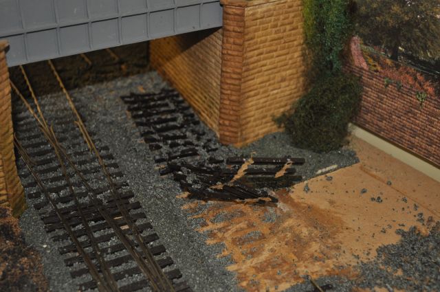
An old saw blade is excellent for clearing the remainder of the granite chips off the railbed and it must be clean to receive the new piece of track or turnout.
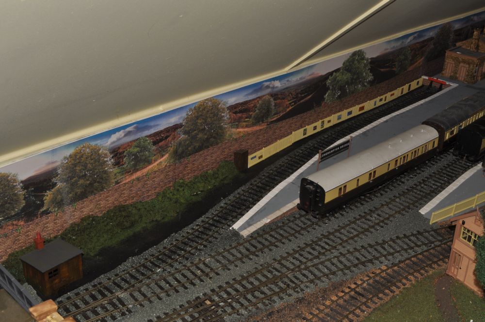
The far end of the rail is just outside of the over bridge and this is where the hole will be cut to accept the pointmotor etc.
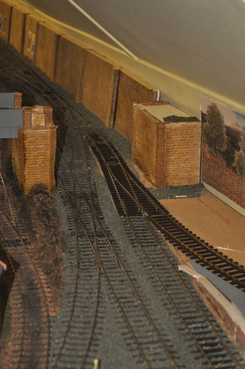
Prior to this, i noticed that the over bridge wall was too close to the turnout. As shown below, this will have to be adjusted. So water is used to soften the PVA. This will allow me to adjust the right hand side of the pillar. It will be the same distance from the track as the rear of this pillar currently is.
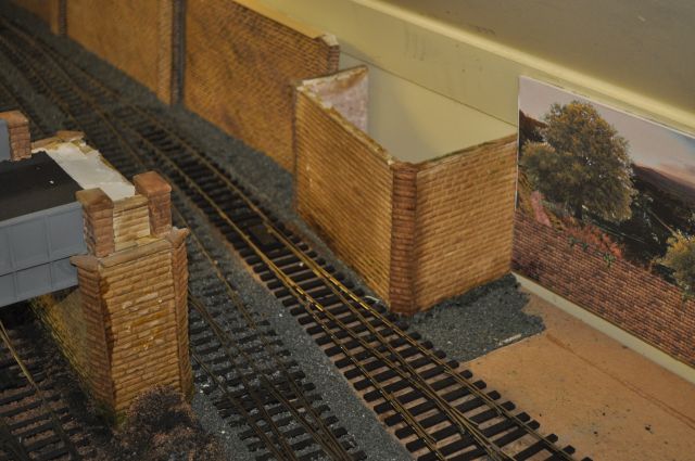
Again you can see how close it is to the track. The issue is that it needs to be parallel to the turn not the straight, as was before.
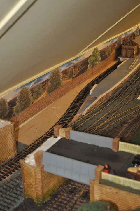
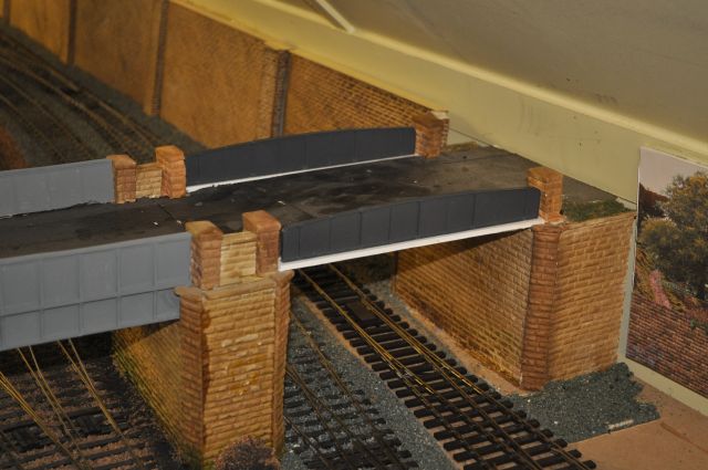
So having adjusted the bridge pillar, it now looks like this:
And looking closer you can see the adjustment that was necessary here. also the bridge span is now wider so I am replacing the existing girders with a new girder section, (PECO stuff for 00 gauge but looks perfect for my purposes), over the main line.
The PECO girder bridge sides were stuck onto a strip of board as shown here.
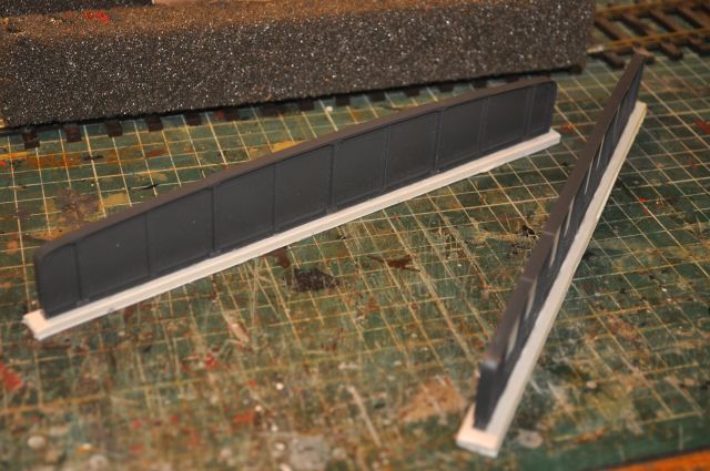
These were then just the right length and width to fit comfortably across the span of the mainline.
Insert the siding rail and adjust the curve accordingly to create clearances for the Steam Railmotor etc. I have extended the siding another 20cms to better accommodate small trains.
The rear platform edging arrived and is glued in place with PVA after some trimming. Also placed the buffer stop in position as shown here:
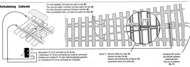
Work on the turnout to upgrade the electrics, see above and click on it to see a larger version, (also click here to see how), adding a point motor, (PL 15, and double micro switch, (PL 10), (the switch will activate the polarity of the switch blades and frog and also work the LEDs in the control panel for this section, (PL 51 and PL 26Y).
Test the new layout and adjust as necessary. Finally make adjustments to the control panel to indicate switch orientation using the second micro switch under the point motor.
Putting the final touches to the siding to finish it off: